Appendix b. wind direction measurement theory, B.1 brhalf instruction, B.1 brhalf – Campbell Scientific 05103, 05103-45, 05106, and 05305 R. M. Young Wind Monitors User Manual
Page 27: Rv v
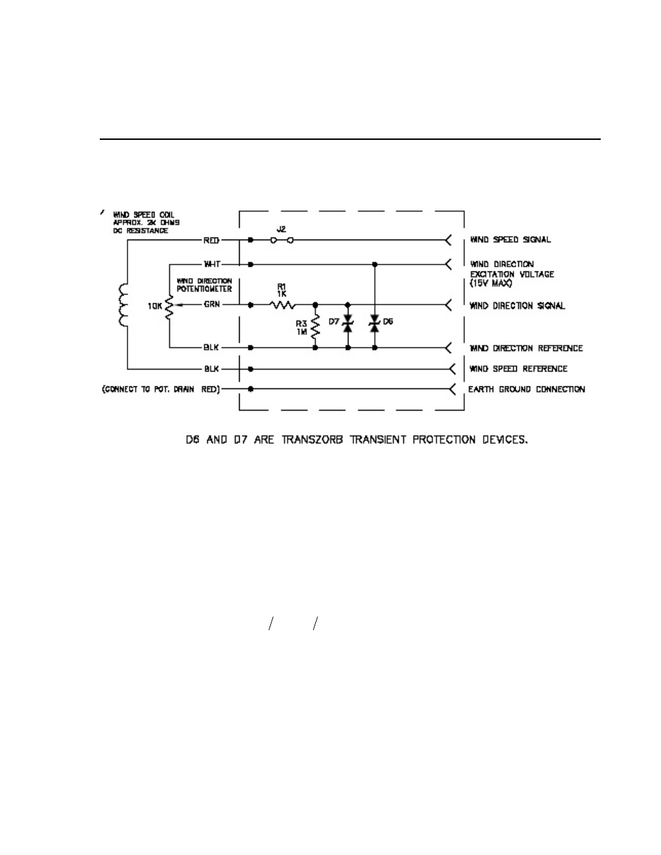
Appendix B. Wind Direction
Measurement Theory
It is not necessary to understand the concepts in this section for the general
operation of the 05103 with Campbell Scientific’s datalogger.
FIGURE B-1. 05103 potentiometer in a half bridge circuit
B.1 BRHalf Instruction
The BRHalf instruction outputs a precise excitation voltage (V
x
), and measures
the voltage between the wiper and ground (V
s
). The resistance between the
wiper and ground, R
s
, and V
s
varies with wind direction. The measurement
result is the ratio of the measured voltage to the excitation voltage (V
s
/V
x
). This
ratio is related to the resistance as shown below:
(
)
s
t
s
x
s
R
R
R
V
V
=
+
The maximum value that R
s
will reach is R
f
, just before it crosses over from the
west side of north to the east side of north (at this point R
t
= 0). V
s
/
V
x
reaches
its maximum value of 1.0 mV/mV at 355 degrees. The multiplier to convert
V
s
/V
x
to degrees is 355 degrees / 1.0 V
s
/V
x
= 355. Since the datalogger outputs
the ratio V
s
/
V
x
, the multiplier is the same for both the CR10(X) and CR3000,
even though they use a different excitation voltage. See Section 13.5 in the
datalogger manual from more information on the bridge measurements.
B-1