3 wiring, 4 programming, 1 wind speed – Campbell Scientific 05103, 05103-45, 05106, and 05305 R. M. Young Wind Monitors User Manual
Page 16: Wiring, Programming, Wind speed, 1. connections to campbell scientific dataloggers
05103, 05103-45, 05106, and 05305 R.M. Young Wind Monitors
7.3 Wiring
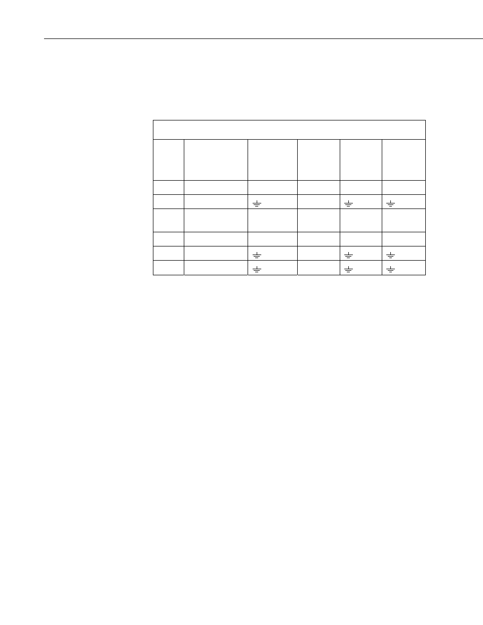
Connections to Campbell Scientific dataloggers are given in TABLE 7-1.
When Short Cut for Windows software is used to create the datalogger
program, the sensor should be wired to the channels shown in the wiring
diagram created by Short Cut.
TABLE 7-1. Connections to Campbell Scientific Dataloggers
Color
Wire Label
CR800
CR5000
CR3000
CR1000
CR510
CR500
CR10(X)
21X,
CR7
CR23X
CR200(X)
Red
WS
Signal Pulse Pulse Pulse P_LL
Black WS
Reference
G
Green
WD Signal
SE Analog
SE
Analog
SE
Analog
SE Analog
Blue
WD Volt Excit
Excitation
Excitation Excitation Excitation
White
WD Reference
AG
Clear Shield
G
7.4 Programming
This section is for users who write their own programs. A datalogger program
to measure this sensor can be created using Campbell Scientific’s SCWin Short
Cut Program Generator software. You do not need to read this section to use
Short Cut.
7.4.1 Wind Speed
For CRBasic dataloggers, wind speed is measured using the PulseCount()
instruction. Syntax of the the PulseCount() instruction is:
PulseCount( Dest, Reps, PChan, PConfig, POption, Mult, Offset )
The PConfig parameter should be set to 1 (Low Level AC) and the POption
parameter should be set to 1 (Frequency).
For Edlog dataloggers, wind speed is measured using Edlog instruction Pulse
(P3). The configuration parameter should be set to code 21 (Low Level AC,
Output Hz configuration).
10