Samlex America ST1500-148 User Manual
Page 17
16
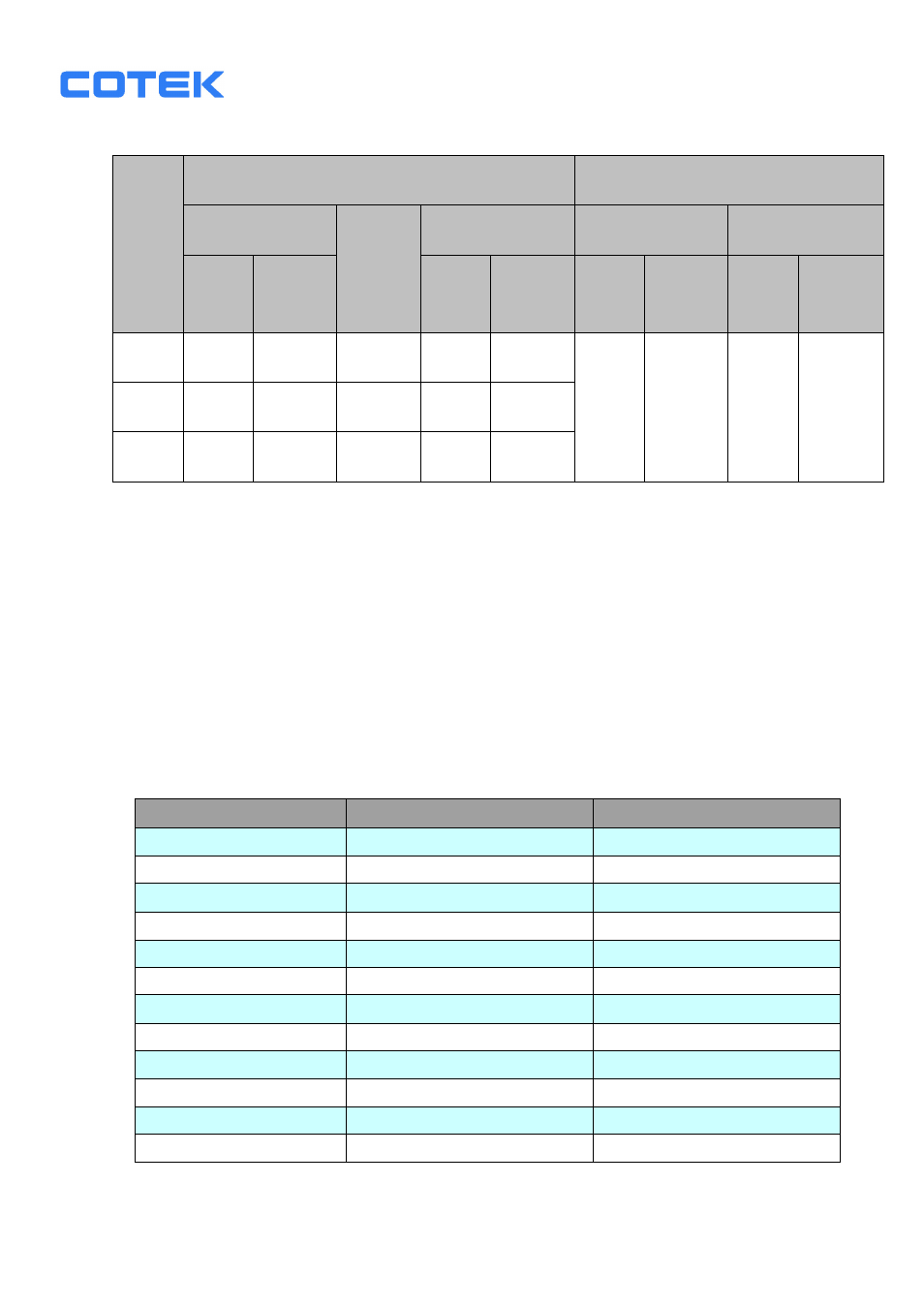
3-2. Protections Features
Model
DC Input (VDC)
Over Temperature Protection
Over Voltage Under
Voltage
Alarm
Under Voltage
INTERIOR
HEAT SINK
Shut-
down
Restart
Shut-
down
Restart Shut-
down
Restart Shut-
down
Restart
12V
15.3
14.3
11.0
10.2
12.7
70℃
45℃
90℃
60℃
24V
30.6
28.6
22.0
20.3
25.2
48V
61.2
57.2
44.0
40.8
49.7
3-3 DC Wiring Connections
Follow the instructions to connect the battery cables to DC input terminals of
the Inverter. The cable should be as short as possible (less than 6 feet / 1.8
meters ideally) so that it can handle the required current in accordance with
the electrical codes or regulations application. Inappropriate length of cables
will deteriorate the inverter performance such as poor surge capability,
frequent low-input voltage warnings, and shutdown. UVP warning occurs
when DC voltage drops across the cables from the inverter to the batteries.
The longer or narrower the cables, the more the voltage drop.
Increasing your DC cable size will help improve the situation.
The following recommended cables are for the best performance of the
inverter. (Apply both 120V and 230V versions)
Model No
Wire AWG
Inline Fuse
ST1000-112 / 212
# 2
150 A
ST1000-124 / 224
# 4
80 A
ST1000-148 / 248
# 6
40 A
ST1500-112 / 212
# 2
200 A
ST1500-124 / 224
# 4
100 A
ST1500-148 / 248
# 6
50 A
ST2000-112 / 212
# 2/0
250 A
ST2000-124 / 224
# 1/0
125 A
ST2000-148 / 248
# 2
70A
ST2500-112 / 212
# 4/0
400 A
ST2500-124 / 224
# 2/0
200 A
ST2500-148 / 248
# 1/0
100 A