Terminal tap table – LBL Lighting 2-Circuit MO Rmt Mag Xfmr 600w 277v/12v User Manual
Page 3
3
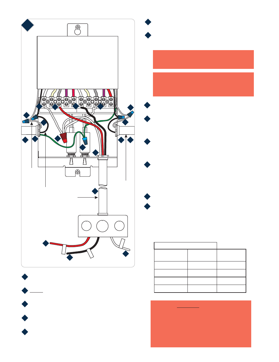
COMX X1
X2
X3
X4 COMY Y1
Y2
Y3
Y4
7
2B
HOT
1
HOT
2
COM
Install the conduit(s) and power line wires from the panel
to remote transformer.
connect the power line wires to the panel at this
time.
Connect the 120V black transformer wire to the hot
power line wire with a wire nut.
Connect the 120V white transformer wire to the neutral
power line wire with a wire nut.
Do not
Connect the ground wire to the green wire or stud
labeled “ground” in the console.
3
4
5
6
HOT POWER
LINE WIRE
NEUTRAL
POWER
LINE WIRE
4
4
CONDUIT
CONDUIT
5
5
6
6
Install a conduit from the transformer to the electrical
box.
For the best performance, use the "Low Voltage Wire
Size Table" on page 2 to select the wire size.
NOTE:
Other wire sizes that comply with electrical
code can be used, but may result in an increased
voltage drop and reduced lamp intensity.
NOTE:
The THHN wire sizes are for 3% or less drop
in voltage based on 300 watt loads. Lengths are the
distance from the transformer to the system power
feed connector.
Install three low voltage wires from the transformer to
the electrical power feed box.
Insert one low voltage wire into the "X2" terminal tap
(default) and tighten the screw firmly. Mark this low
voltage wire in the electrical power feed box as
"HOT 1".
Insert the second low voltage wire into the "COMY"
terminal and tighten the screw firmly. Mark this low
voltage wire in the electrical power feed box as
"HOT 2".
Cut two short pieces of low voltage wires (THHN). Insert
one short low voltage wire into "COMX" terminal and
the other one into "Y2" terminal tap (default) and tighten
the screws. Connect these two short wires to the third
low voltage wire with a wire nut. Mark this low voltage
wire in the electrical power feed box as "COM".
Connect the 120 volt power line wires at the panel.
Measure the voltage at the power line wires coming into
the transformer. If the voltage is not in the range of
115 - 120 volt, then pick the proper terminal tap using
the "Terminal Tap Table" below to reconnect the low
voltage wire that was connected to "X2" and the short
wire that was connected to "Y2" terminal taps.
PRIMARY POWER
LINE VOLTAGE
105 - 109
TERMINAL TAP TABLE
110 - 114
115 - 120
121 - 125
TERMINAL TAP
TO BE USED
X4
X3
X2
X1
8
9
10
11
12
13
14
WARNING:
-
Risk of Fire
The terminal taps are not
for boosting the transformer low voltage power, they
are selected to ensure power output voltage based
upon power line conditions. Never use a higher
terminal tap to compensate for voltage drop, this may
overheat the low voltage wires and transformer. It is
recommended to use the wire size as indicated on
"Low Voltage Wire Size Table" on page 2 to avoid
excessive voltage drop.
8
10
11
11
12
12
13
13
13
13
14
14
15
TERMINAL TAP
TO BE USED
Y4
Y3
Y2
Y1
7