2 determining the permitted speed of rotation, Important – ROHM KFD-HE - Power chucks with through-hole User Manual
Page 14
7. Calculating the clamping force and speed of rotation
7.1 Determing the clamping force
7.3 Permitted speed of rotation
The following formula applies for determining the
permitted speed of rotation for a specific machi-
ning job:
n
perm
=
[min
--1
]
(Note the number of jaws for Σ M
c.
)
(9)
.
n
7.2.1 Centrifugal force F
c
, and centrifugal moment M
c
Formulae (1), (2) and (3) produce the following result
for clamping from the outside in:
F
sp
=
-- F
c
[N]
(4)
In this case the centrifugal force F
c
is dependent on
the mass of all jaws m
B
, the centre of gravity radius r
s
and the speed of rotation n.
The following formula can be derived:
F
c
= (m
B
.
r
s
)
.
(
) [N]
(5)
The expression m
B
⋅
r
s
is called the centrifugal
moment M
c
M
c
= m
B
.
r
s
[mkg]
(6)
The following formula applies to chucks with sliding
and false jaws in which the false jaws AB can be mo-
ved in order to alter the clamping area and the sliding
jaws GB approximately maintain their radial position:
M
c
= M
cGB
+ M
cAB
[mkg]
(7)
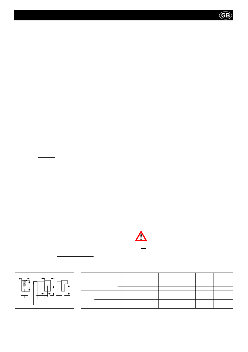
M
cGB can be obtained from the table below.
M
cAB can be calculated using the following formula:
M
cAB
= m
AB
⋅
r
sAB
[mkg]
(8)
The clamping forces can be obtained by referring to
the clamping force/speed of rotation diagram (see
page 28) when using standard series production
jaws allocated to specific chuck by the chuck
manufacturer.
F
spo
S
sp
π
30
30
π
Do not exceed the maximum speed of rotation
n
max
of the chuck (marked on the body of the
chuck). This applies even if the calculated
permitted speed of rotation n
perm
is greater than
the maximum speed n
max
.
7.2 Determining the permitted speed of rotation
2
The clamping force F
sp
of a rotary chuck is the total of
all jaw forces acting radially on the workpiece. The
clamping force applied before the cutting process and
with the chuck stationary is the initial clamping force
F
spo
. The clamping force F
sp
avialable during the cutting
process is, firstly, the initial clamping force F
spo
existing
with the chuck stationary. This force is then increased or
decreased by the centrifugal force F
c
on the jaws.
F
sp
= F
spo
F
c
[N]
(1)
The (--) sign is for clamping forces applied from the
outside in.
The (+) sign is for clamping forces applied from the
inside out.
The clamping force F
sp
avialable during the cutting
process multiplied by safety factor S
z
²
1,5.
The size of this factor is determined by the accuracy of
the influence parameters such as loading, clamping
coefficient, etc.
F
sp
= F
spz
.
S
z
[N]
(2)
A safety factor of S
p
²
1,5 should be taken into
consideration for the static initial clamping force F
spo
.
Consequently, the following applies for the clamping
force with the chuck stationary.
F
spo
= S
sp
.
(F
sp
F
c
) [N]
(3)
The (--) sign is for clamping forces applied from the
outside in.
The (+) sign is for clamping forces applied from the
inside out.
F
spo
-- (F
spz
.
S
z)
M
c
Important:
A
54
66,7
75
95
95
Max. weight in kg
0,22
0,7
0,88
1,4
1,4
Chuck size
130
170
210
254
315
400
at
max
.
speed
B
A
C
huck
C
o/
LA
RA
rs
B
23
36,5
36,5
45
45
C
29
53
53
54,5
54,5
R
a
max. in mm
39
52
68
80
110
L
a
max. in mm
18
29
29
30
30
Centrifugal moment M
C
GB [mkg]
0,015
0,030
0,051
0,125
0,300