Mounting the chuck on the machine spindle, Maintenance – ROHM KFD-HE - Power chucks with through-hole User Manual
Page 13
3. Mounting the chuck on the machine spindle
1. Mounting the chuck on the machine spindle
1.1 Check the machine spindle or the machine-mounted
finished-machined adapter plate for radial and axial
run-out (permissible tolerance 0,005 mm to DIN 6386
and ISO 3089).
1.2 The adapter plate must be designed so that the
chuck makes full contact with the plate face.
The plate or spindle face must be perfectly flat.
2. Mounting a size 130 and 170 chuck
2.1 Move piston of clamping cylinder with draw tube to
extreme forward position.
2.2 Pull clamping piston (3) in chuck into extreme rear-
ward position (jaws in extreme internal position).
2.3 Screw power chuck on to draw tube as far as it will
go (making sure that the draw tube thread is poperly
aligned).
2.4 Screw chuck back until bore is aligned with positio-
ning element of spindle nose or fastening holes with
fastening screw threads.
2.5 Push chuck against spindle nose or adapter plate
and alternately tighten chuck mounting screws (15).
2.6 Check performance, jaw travel andactuating force.
3. Mounting other chucks (size 210 and above)
3.1 Move piston of clamping cylinder with draw tube to
extreme forward position.
3.2 Remove protective bushing (4) from chuck.
3.3 Screw chuck with rotatable threaded bushing on to
draw tube.
3.4 Push chuck against spindle nose or adapter plate
and alternately tighten mounting screws (15).
3.5 Move piston of clamping cylinder to extreme forward
position, check clearance (1 mm) between piston (3)
and chuck body (1) and correct position of piston by
turning the threaded bushing if necessary.
3.6 Screw on protective bushing and check performance,
jaw travel and actuating force.
3.7 Check mounted chuck for radial and axial runout (at
checking edge).
Removing the chuck is carried out in the
reverse order.
4. Maintenance
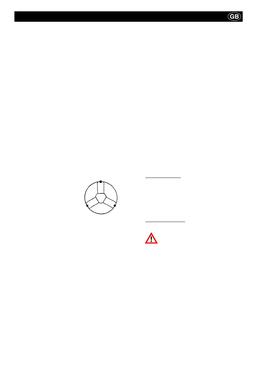
1. To maintain its reliability and
high quality, the chuck must
be lubricated at the grease
nipples at regular intervals
(see illustration).
After lubrication, move the
clamping piston several times
over its full stroke in order to
distribute the grease more
evenly. Then lubricate again.
2. Performance and clamping force must be checked
after some time, depending on the conditions of use.
The most reliable method of measuring the clamping
force is by means of a load cell.
3. Performance check: The clamping piston must
move when the lowest possible actuating pressure of
3-4 bar is applied. However, this method is not relia-
ble enough to serve as a substitute for the clamping
force measurement.
If the clamping force has dropped substantially or
if the clamping piston can no longer be moved with
ease, the chuck must be disassembled, cleaned
and relubricated.
4. Maintenance intervals: Depending on the conditions
of use, but not later than after the specified periods.
We recommend our special grease F 80.
Lubricate all lubricating points
every 20 hours of operation
heavy soling every 8 hours.
Disassemble the chuck and clean all parts
every 2000-3000 hours of operation.
1. Remove protective bushing (4) from chuck.
2.If applicable, unscrew mounting screws (18) and re-
move intermediate flange (7).
3. Pull out clamping piston (3).
4. Unscrew mounting screws (17), remove stop ring (6)
and ring nut.
5. Pull out base jaws (2), each jaw separately, from out-
side to inside.
6. To assemble the chuck, reverse the procedure des-
cribed above, making sure that the individual parts
are correctly numbered.
5. Disassembly and assembly of the chuck
6. Spare parts
When ordering spare parts, please quote the Ident. No. of the chuck and the item number or designation of the desired part
(see page 3). -- The Ident. No. will be found on the face of the chuck.