2 connections, 1 connector pinout – Matrix Orbital LCD2041 Legacy User Manual
Page 5
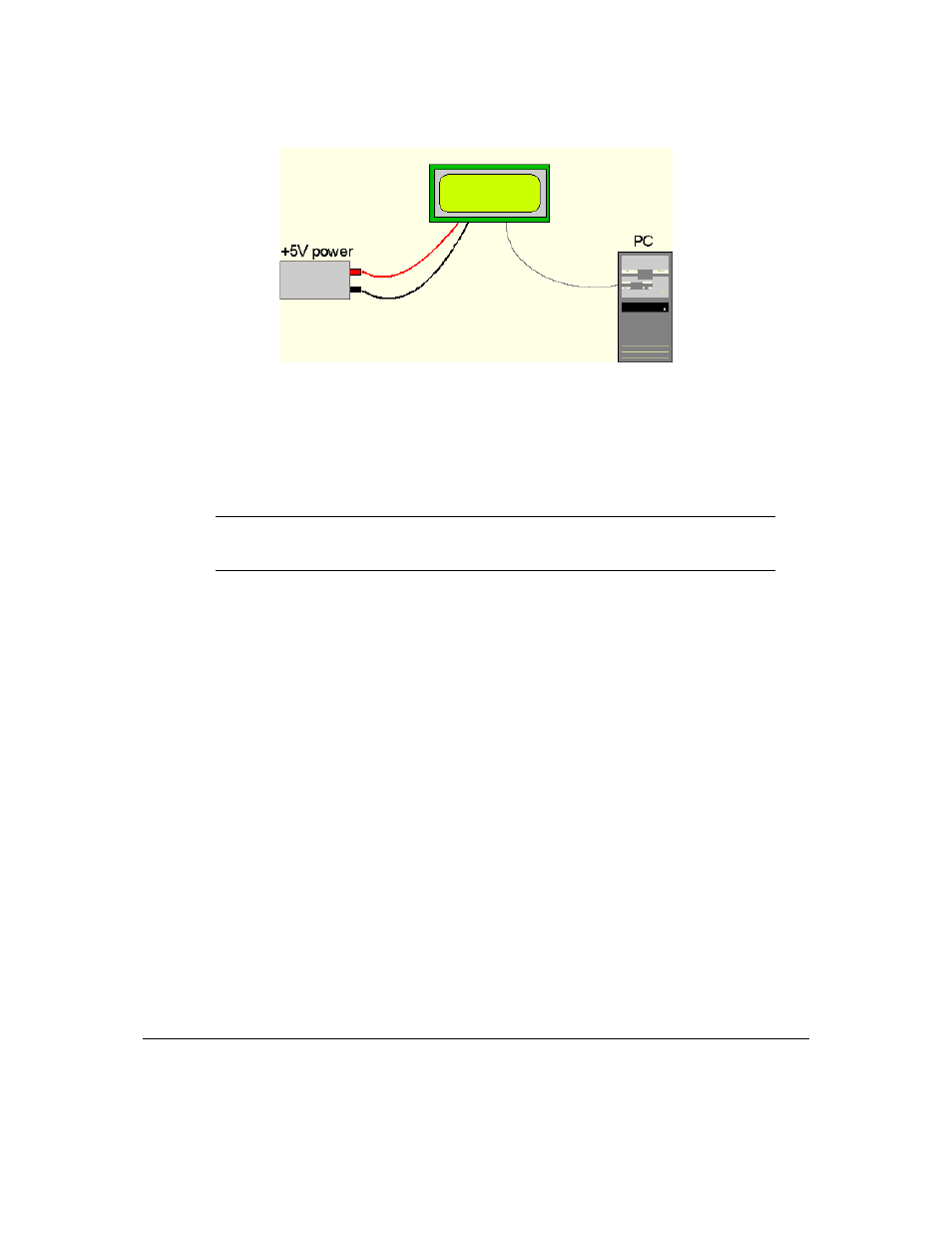
Figure 1: Connections for Testing
1. Refer to the Figure above for the following steps.
2. Wire the connector to the power supply. On most connectors the RED lead will go to +5V and the
BLACK lead to GND.
NOTE The Manufacturer’s Warranty becomes void if the unit is subjected to over-voltage
or reversed polarity.
3. Connect the display to the PC using the serial cable and adapter if required. Make sure the RS-232
cable includes the required ground lead. There must be no voltage differential between the RS-232
ground and the power supply ground.
4. Connect the power connector, making sure that the +5V goes to V+ . Turn on the power; the display
backlight should come on and a blinking cursor at the top left should appear.
1.4 Trying out the LCD2041
The unit should be connected to power and the PC and backlight should be on. To experiment with
typing text, run a PC program such as Display Tuner or AlphaDemo. Make sure it’s configured to use the
correct port. Set the baud rate to 19,200.
To exercise some of the other features of the display, a program (in any convenient language such as
Basic or C) will need to be written in order to issue the required command strings. Most terminal programs
are unable to issue the 0xFE character needed as a command prefix.
2 Connections
2.1 Connector Pinout
Refer to the Figure below for this chapter.
Matrix Orbital
LCD2041
2