Warning, Connections, 1 connector pinout – Matrix Orbital LK202-25 Legacy User Manual
Page 8: Do not apply any power with reversed polarization, 1 power and i, C connections
LK202-25 rev 3
8
2. Connections
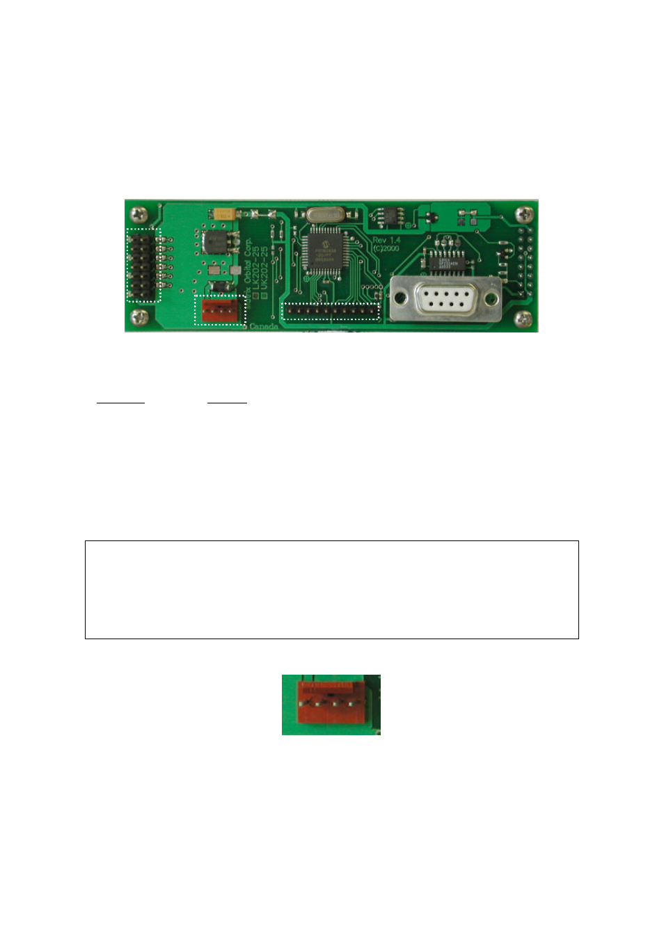
2.1 Connector Pinout
Refer to the diagram below for this chapter.
Key pad
Connector
Powe r
connecto r
Ge neral
Purpose
Outputs
RS -232
pin 1
+5
gnd
pin 1
pin 5
1
2
3
4
5
6
Figure 2-1 Electrical Connections
The LK202-25 has four connectors:
Connector
Function
14 pin dual header
General purpose outputs (6) (see section 2.2)
4 pin
power (5.0 VDC) and I
2
C communications (see section 2.1.1)
10 pin header
Keypad (see section 3.4.12)
DB-9F
RS-232/power (see section 2.1.1.1)
2.1.1 Power and I
2
C Connections
Power is applied via pins 1 and 4 as shown in Figure 2-1. Power requirement is +5 VDC ±0.25V. Power
may also be supplied via the RS-232 connector as described in the next section.
Warning:
§
Do not apply any power with reversed polarization.
§
Do not apply any voltage other than the specified voltage.
§
Do not use any cables other than the cables supplied by Matrix Orbital,
unless you are aware of the modifications required.
Connector pinout is as follows:
1 2 3 4
Figure 2-2 Power connector
Pin 1
+5.0 VDC (+7 to +15 VDC with wide voltage option)
Pin 2
SCL (I
2
C clock)
Pin 3
SDA (I
2
C data)
Pin 4
Ground