Matrix Orbital LK202-25 Legacy User Manual
Page 11
LK202-25 rev 3
11
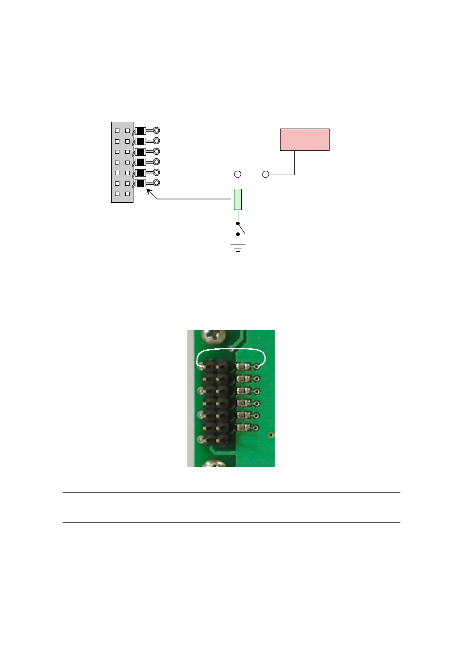
Each output is wired as shown in Figure 2-8. The + terminal is connected directly to the module positive
supply, the – terminal is connected through a 240 ohm current limiting resistor and the electronic switch
to ground.
+ 5 VDC
240 ohm current limiting resistor
load
+
-
+
-
G PO 1
G PO 2
G PO 3
G PO 4
G PO 5
G PO 6
Pow e r
Figure 2-8 General Purpose Outputs
Maximum allowable current is 20 mA, which is enforced by the current limiting resistor. If the device
being switched has a resistance of 240 ohms or more the corresponding resistor may be shorted. Solder a
small jumper wire (wirewrap wire is good) from the feedthrough hole to the corresponding negative pin
for the GPO in question.
Jumper wire
Figure 2-9 Bypassing 240 ohm resistor
Note: The GPOs do not have any over current or over/under voltage protection so care must be taken
when using them. For instance if the external device is a relay it must be fully clamped (using a diode and
capacitor) to absorb any generated back electro-motive force (EMF).