Matrix Orbital LK202-25 Legacy User Manual
Page 5
LK202-25 rev 3
5
§ A power cable with a 4 pin connector (same connector as used to connect 3.5 inch floppy
drive). Do not connect the LK202-25 to an unmodified spare power connector in a PC. To
modify such a cable see section 2.1.1.
§ A 5 V power supply.
§ a PC with a spare RS-232 port (COM1 or COM2).
§ A 9 or 25 pin RS-232 serial cable. If you use a 25 conductor cable you'll also need a 9 to 25
pin adapter.
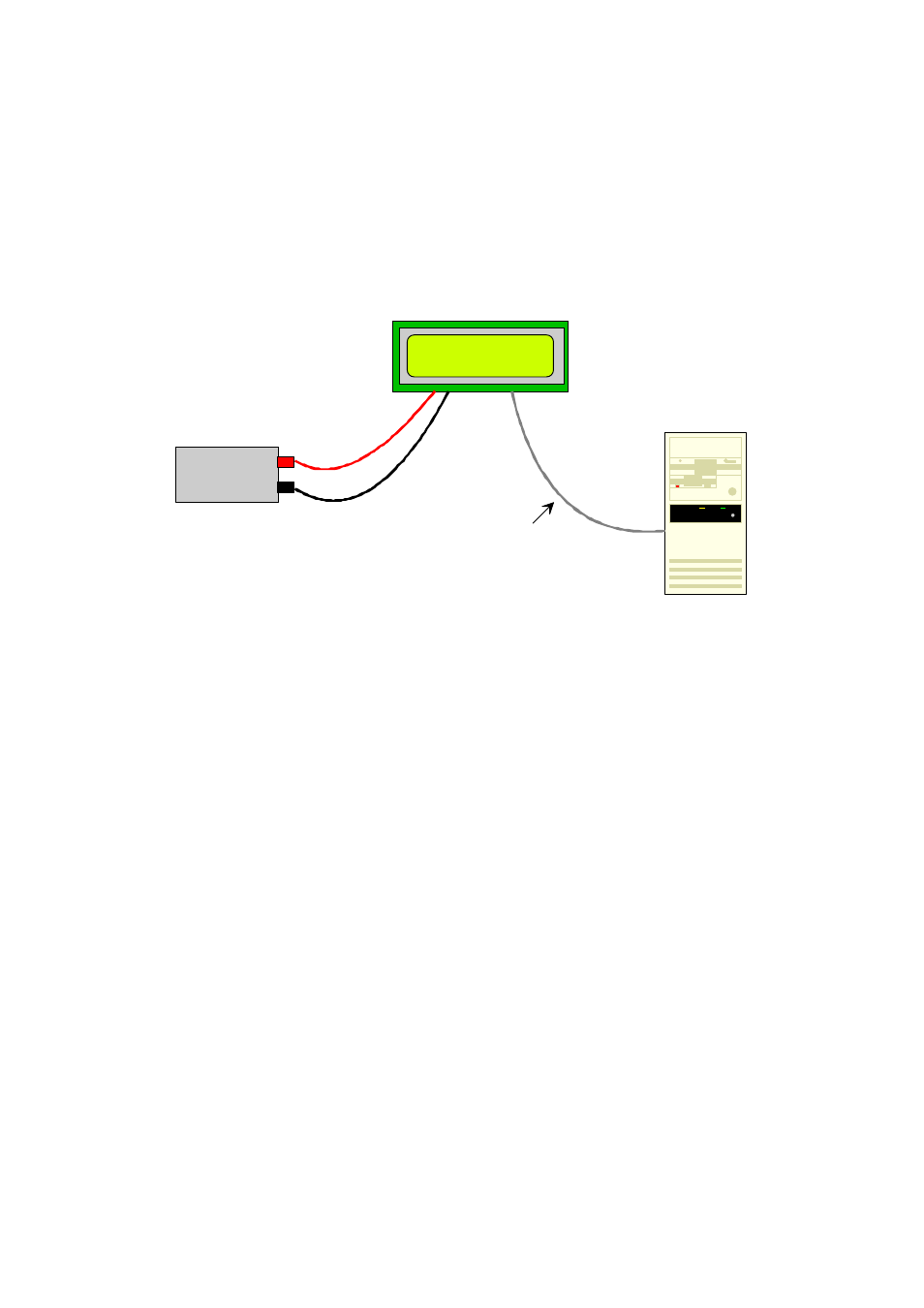
+5V power
LK202-25
PC
RS-232 cable
Figure 1-1 Connections for Testing
1. Refer to the diagram above and Figure 2-1 for the following steps.
2. Wire the connector to the power supply. On most connectors the RED lead will go to +5V and the
BLACK lead to GND. See Section 2.1.1 for details.
Note: The manufacturer's warranty is void if
the unit is subjected to over-voltage or reversed polarity.
3. Connect the LK202-25 to the PC using the serial cable and adapter if required. Make sure the RS-
232 cable includes the required ground lead. There must be no voltage differential between the
RS-232 ground and the power supply ground.
4. Connect the power connector, making sure that the +5V goes to V+ as shown in Figure 2-2. Turn on
the power: the LCD backlight should come on.
Now you're ready to try it out.
1.5 Trying Out your LK202-25
The unit is connected to power and the PC and the backlight is on. You're ready to make sure it's working
properly.
§ To experiment with typing text, run a PC terminal program, such as Hyperterm. Make sure it's
configured to use the correct port. Set the baud rate to 19,200.
If you type characters on the keyboard, they should now appear on the LK202-25 screen. Text will wrap
around to the next line when you reach the end of a line. A few common ASCII control characters work as
follows: