L-series snap action switches for pressure control – Ashcroft L - Pressure switches User Manual
Page 2
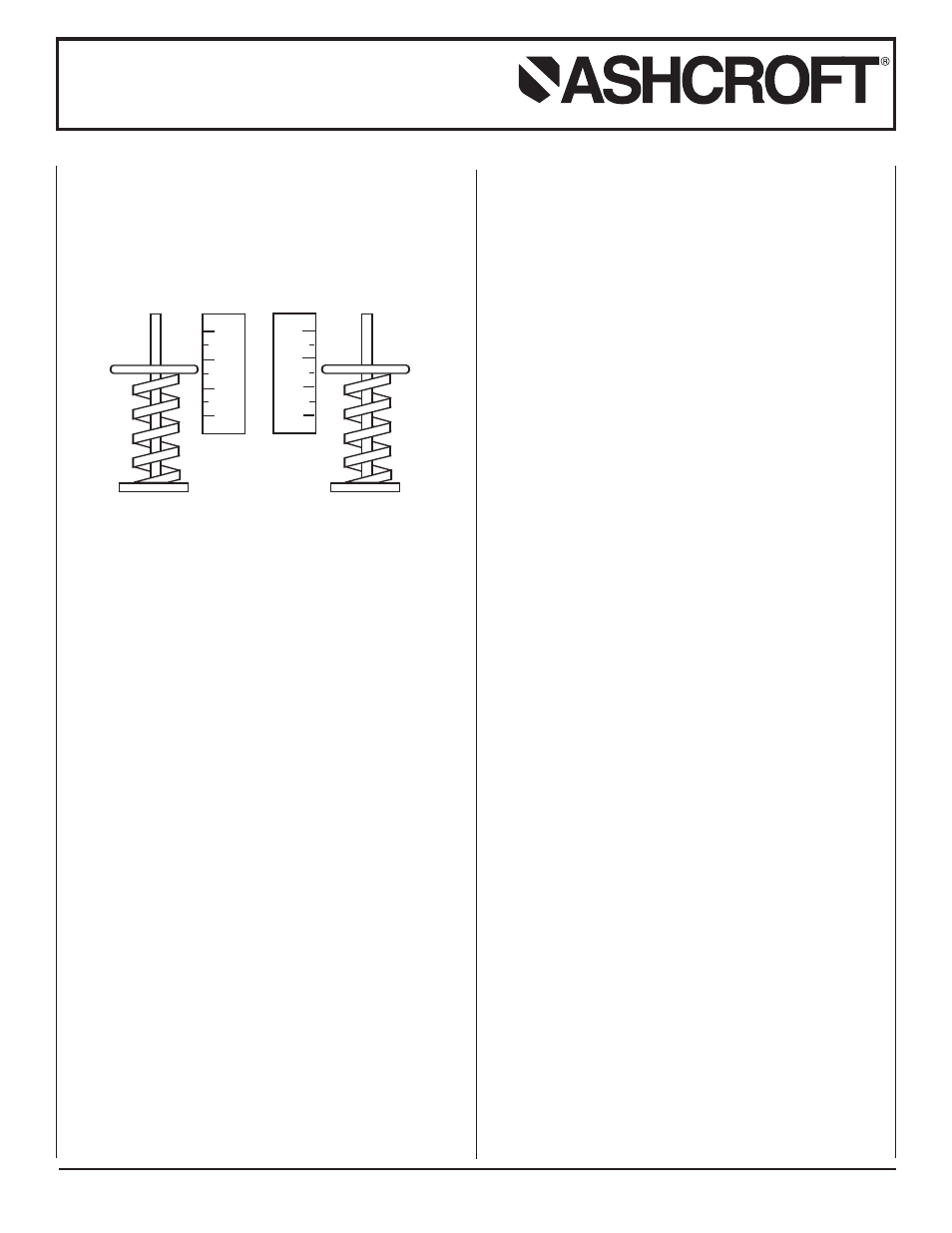
SETPOINT ADJUSTMENTS
Setpoints are changed by means of the setpoint adjusters The
LP-S single switch has one adjuster and the LP-A adjustable
deadband and LP-D dual switch each have two adjusters. On
switches with two adjusters, the one on the left is referred to as
“A” and the right one is referred to as “B”; see illustration.
Setpoints can be adjusted from 15 to 100 percent of full range
on increasing pressure.
SERIES LP-S SINGLE SWITCH
Remove cover. For setpoint adjustment on either increasing or
decreasing pressure to within ±1% of nominal range, mount the
switch on a calibration stand and use a suitable reference such
as an ASHCROFT
®
Duragauge or test gauge. Monitor switch
with a light or meter. Pressurize the system to the required set-
point pressure.
If setpoint is on increasing pressure, turn adjuster so that
switch operates (if common – normally closed circuit is being
monitored light goes off). If setpoint is on decreasing pressure,
turn adjuster so that switch resets (if common – normally closed
circuit is being monitored light comes on). When the setpoint
has been achieved, raise and lower the pressure to ensure that
the setpoint is correct.
The deadband (difference between the operate and reset
pressures) may be verified at this time to be between the values
noted on the nameplate label.
SERIES LP-D DUAL SWITCH
Remove cover. For setpoint adjustment on either increasing or
decreasing pressure to within ±1% of nominal range, mount the
switch on a calibration stand and use a suitable reference such
as an ASHCROFT
®
Duragauge or test gauge. Monitor switch
with a light or meter.
Pressurize the system to the required higher setpoint pressure
and turn adjuster “B” until the switch operates or resets as
required. See discussion of increasing or decreasing pressure
setpoints and deadband verification under Series LP-S Single
Switch. When the setpoint has been achieved, raise and lower
the pressure to ensure that the setpoint is correct. Then reduce
system pressure to the required lower setpoint pressure and
turn adjuster “A” until the switch operates or resets as required.
Verify this setpoint by raising and lowering pressure. Now
increase system pressure to higher setpoint and make final
adjustment on “B.”
Installation and Maintenance Instructions
for ASHCROFT
®
L-Series Snap Action
Switches for Pressure Control
A
B
0
20
40
60
0
20
40
60
SERIES LP-A ADJUSTABLE DEADBAND SWITCH
Remove cover. Adjuster “B” controls the operating point of
the switch on increasing pressure. Adjuster “A” controls the
re-setpoint of the switch on decreasing pressure.
For accurate setpoint adjustment, mount the switch on a
calibration stand and use a suitable reference such as an
ASHCROFT
®
Duragauge or test gauge. Monitor switch with a
light or meter. Pressurize the system to the required setpoint
pressure. Turn adjuster “B” until switch operates. Then lower
pressure to the re-setpoint, turn adjuster “A” until the switch
resets. Now increase pressure to the operating point and make
final adjustment on “B”. Raise and lower pressure to ensure that
the setpoint and re-setpoint are correct.
SOME PRECAUTIONS TO OBSERVE
Do not loosen the screws holding the precision switch element(s)
or mounting bracket in place.
Nameplate PROOF pressure should not be exceeded. Inter-
mittent operation up to proof pressure is permissible, however,
some change of setpoint may be noted.
Operation and correct setpoint actuation should be routinely
tested.
Note – Since vacuum models are already above setpoint at
atmosphere, the Normally Open (NO) circuit will be
closed as received.
© 2007 Ashcroft Inc., 250 East Main Street, Stratford, CT 06614-5145, USA, Tel: 203-378-8281, Fax: 203-385-0499, www.ashcroft.com
All sales subject to standard terms and conditions of sale. All rights reserved. I&M009-10015-10/00 (250-2870) AMR 12/07