Ashcroft L - Pressure switches User Manual
L-series snap action switches for pressure control, Operation the ashcroft, Psi ranges in.h
Installation and Maintenance Instructions
for ASHCROFT
®
L-Series Snap Action
Switches for Pressure Control
OPERATION
The ASHCROFT
®
pressure control is a precision device which
features a snap action switch. Fixed deadband is available with
single or dual SPDT independently adjustable switches with
various electrical ratings. Adjustable deadband is available with
SPDT switch with various electrical ratings. Several wetted
material constructions for compatibility with pressure media may
be obtained.
Series LP-S switches have a fixed deadband which will be
within the limits noted on the nameplate.
Series LP-D switches may be set to operate simultaneously or
up to 85 percent of the range apart. The deadband of each
switch will be within the limits noted on the nameplate.
Series LP-A switches may be set to operate with any
deadband within the limits shown on the nameplate.
MOUNTING
The “L” Series ASHCROFT snap action pressure switch has a
NEMA-4 enclosure which is an epoxy coated aluminum casting.
Two holes in the integral bracket are used to surface mount
the control. Location of these holes is shown on the general
dimension drawings. An optional pipe mounting bracket is also
available. Mount on a vibration free surface or pipe in any orien-
tation. When tightening control to pressure line, always use the
wrench flats or hex on the pressure connection. NEVER
TIGHTEN BY TWISTING THE CASE.
CONDUIT CONNECTIONS
One
3
⁄
4
NPT hole fitted with a shipping plug, and two additional
knock outs are provided. The knockouts may be removed by
placing a screwdriver in the slot and rapping sharply with a
hammer It is recommended that Teflon tape or other sealant be
used on conduit bushings or plug threads to ensure integrity of
the enclosure.
ELECTRICAL CONNECTION
Remove cover, held in place by two screws.
On all units except one with terminal blocks – wire directly to
the switch according to circuit requirements. Units with terminal
blocks – wire directly to terminal blocks as required. Terminals
are marked common (C), normally open (NO) and normally
closed (NC).
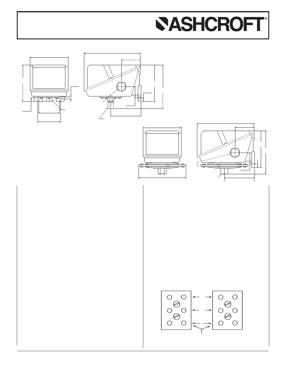
4.12
(105)
2.25
(57)
2.50
(64)
0.25
(6)
3.98
(101)
0.43
(11)
PRESSURE PORT
1/4 NPT FEMALE
6.09
(155)
2.06
(52)
3.26
(83)
1.21
(31)
0.38
(10)
3.94
(100)
4.72
(120)
3/4 NPT
X06
1/2 NPT MALE &
1/4 NPT FEMALE
4.12
(105)
Ø 5 .
12
(130 )
3.2 6
(83)
4.65
(1 1 8
)
3.94
(1 0 0
)
0.38
(1 0
)
1.2 1
(31 )
2.06
(52 )
6. 09
(155 )
3/4 NPT
1/4 NPT
FEMALE
psi Ranges
in.H
2
O Ranges
1
2
3
1
2
3
LEFT SWITCH
TERMINAL BLOCK
RIGHT SWITCH
TERMINAL BLOCK
SERVICE LEADS TO THESE TERMINALS
NC
NO
C
STANDARD RANGES
15, 30, 60, 100, 200, 400, 600 psi
*1000, 2000, 3000 psi
30˝Hg vac.-0 psi
STANDARD RANGES
30, 60, 100, 150 in.H
2
O
15 in.H
2
O-15 in. H
2
O
2.7 lbs.
3.4 lbs.
© 2007 Ashcroft Inc., 250 East Main Street, Stratford, CT 06614-5145, USA, Tel: 203-378-8281, Fax: 203-385-0499, www.ashcroft.com
All sales subject to standard terms and conditions of sale. All rights reserved. I&M009-10015-10/00 (250-2870) AMR 12/07