Installation, Wiring – Ashcroft GC31 - Digital Pressure Sensor User Manual
Page 8
8
3. INSTALLATION
Install in a location where vibration and shock can be minimized and without direct sunlight on
the display in compliance with IP40 environmental rating.
(Pressure port connection:
1
⁄
4
NPT male 1
1
⁄
2
turns hand tighten.)
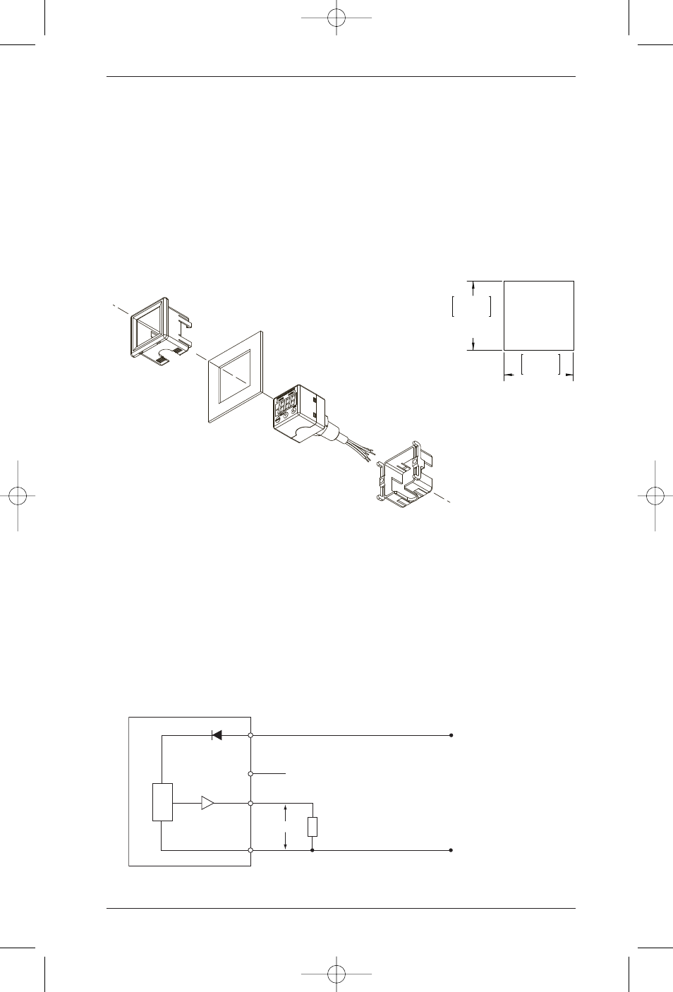
Note: Panel mount adapter for back connection only. Do not attach panel mount adapters
prior to panel installation or out of sequence as stated below.
1.) Take Panel Adapter #1 (tube notch faced down) and mount to the main body with panel placed
in between as pictured. Push adapter and main body together until tabs engage notches.
2.) Take Panel Adapter #2 (tube notch faced down) and attach to the back of the main body. Push
until panel adapter tabs engage the main body notches.
3.) Gently push panel adapters together until gaps are minimized.
4. WIRING
Cable wire colors are shown below. Power on after checking connections. when on wait at
least 5 minutes before performing a zero point adjustment or measurement to ensure system
is stabilized.
Brown……………………………..
Power (+)
Blue……………………………….
Power (–)/COM
Orange……………………………. Analog output (+)
Black………………………………
Open collector output OUT 1 (+)
White……………………………… Open collector output OUT 2 (+)
Analog Output (1-5VDC)
GC31
(Brown)
(Black-White)
(Orange)
(Blue)
Load
10k
⍀ min.
Power (+)
Power (–)
1-5Vdc
1.42
– .0000
+ .0236
36
0
+ 0.60
1.42
– .0000
+ .0236
36
0
+ 0.60
Panel cutout
dimension
Front of Panel
Panel
Adapter #1
Panel
Adapter #2
Back of Panel
Panel Cutout
Main Body
I&M011-10170 GC31:layout 4/8/10 3:26 PM Page 8