Z s z s, Z” and “s” pots – Ashcroft A4 - Pressure Transmitter User Manual
Page 4
Power Supply
Power Supply Voltage
Output Signal
Min
Max
4-20mA*
12V**
30V
* Refer to Ashcroft drawing #825A022 for
supply voltage and load limit.
** The minimum voltage at the terminals is
12Vdc. However, the minimum supply
voltage should be calculated using the
following graph and formula.
A4 INTRINSICALLY SAFE &
NON-INCENDIVE RATED
PRESSURE TRANSMITTER
INSTRUCTION SHEET
Mounting
The A4 transmitter requires no special
mounting hardware, and can be mounted
in any plane with negligible position error.
Although the unit can withstand normal
vibration without damage or significant
output effects, it is always good practice
to mount the transducer where there is
minimum vibration.
For units with NPT type pressure fittings
apply Teflon
®
tape or an equivalent
sealant to the threads before installing.
When tightening, apply a wrench to the
hex wrench flats located just above the
pressure fitting. DO NOT tighten by using
a pipe wrench on the housing.
Noise
For minimum noise susceptibility, avoid
running the transducer’s cable in a con-
duit that contains high current AC power
cables. Where possible avoid running
the cable near inductive equipment.
Shielded Cable
Units with shielded cable electrical termi-
nation, connect the drain wire to the
guard terminal on the read out device or
measuring instrument, if available. In all
other cases connect to the ground or to
the power supply negative terminal.
Vent Tube (Cable Termination Only)
The cable has a clear Teflon
®
vent tube
required at pressure ranges below 500
psi to provide atmospheric reference.
The open end should be placed in a
dry area.
+
+
–
POWER
SUPPLY
(+)
(–)
TRANSDUCER
–
V+
V–
PIN 1
PIN 2
4-20mA
METER
OR OTHER DEVICE
A4 Wiring Diagrams
Zero and Span Adjustment
Instructions below apply to the particular
configurations noted. While Zero adjust-
ment is not normally necessary, it may be
desirable to trim out any offset in the sys-
tem. However, proper Span calibration
requires a pressure standard three to five
times more accurate than the accuracy of
the transducer, and there may also be
interaction of Span on Zero.
A4 transducer has internal transient
protection: for safety, limit line-to-
ground voltage to 36 Vdc max.
© 2011 Ashcroft Inc. All rights reserved. 250 East Main Street, Stratford, CT 06614 USA Tel: 203-378-8281, Fax: 203-385-0402 www.ashcroft.com
All sales subject to standard terms and conditions of sale. I&M011-10166-A4. Rev. 12/12
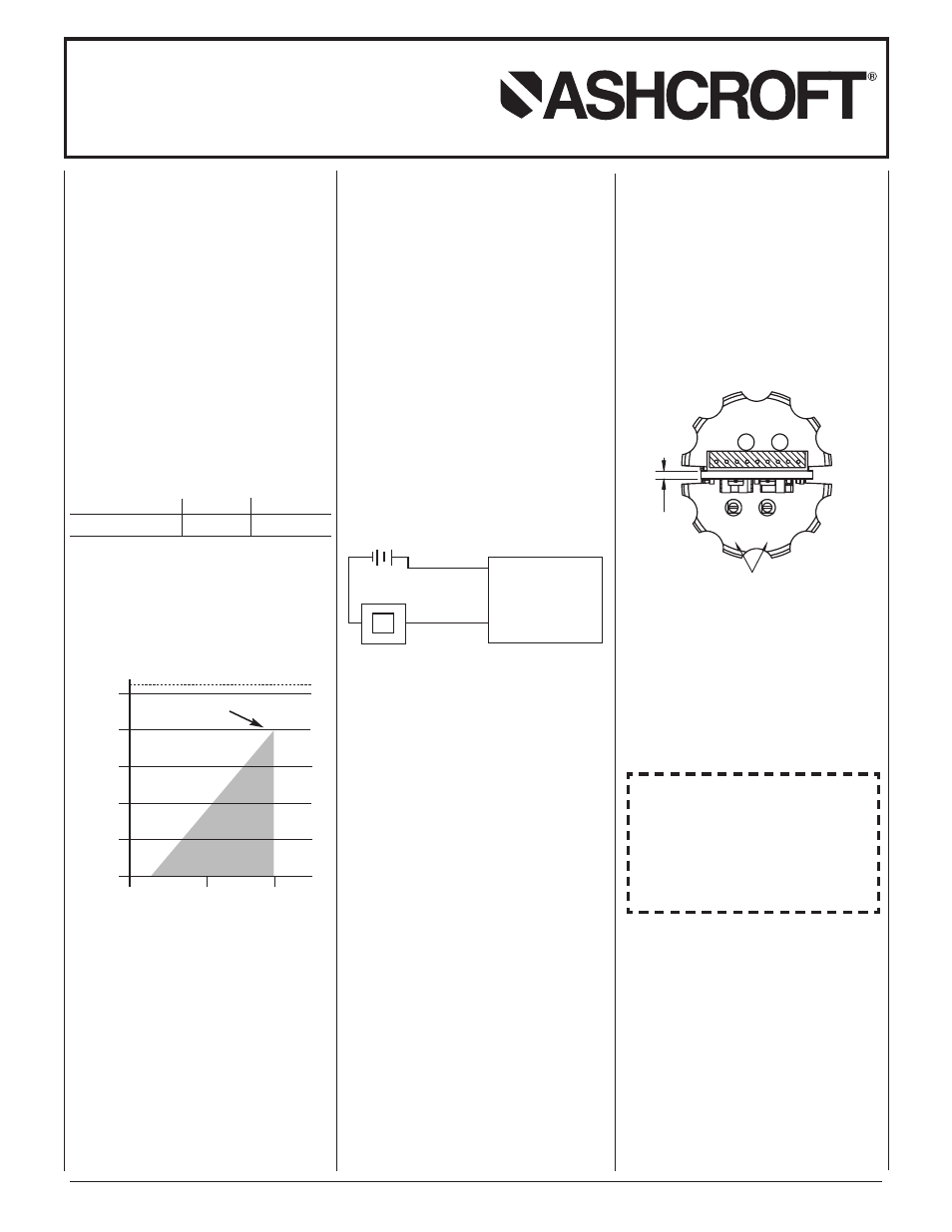
A4 configurations with enclosure “S”
offer Zero and Span potentiometer
access.
Access to “Z” and “S” pots via the top
(electrical termination end) of the unit is
standard on all “S” enclosure units with 4-
20mA output. Access is gained by remov-
ing the black threaded cap, once removed
you will see the pots indicated by “Z” and
“S” respectively as shown below. Using a
small trim pot tool, you can adjust zero
±10% of full scale and span ±10% of
full scale.
Recalibration Instructions:
1. Apply 0% full scale pressure.
2. Adjust the output using the zero adjust
trim pot.
3. Apply 100% full scale pressure.
4. Adjust the output using the span adjust-
ment trim pot.
5. Repeat steps 1 through 4 as necessary.
.
0
6
2
Z S
Z
S
“Z” and “S” pots
Vmin = 12V+ (.022A x RL) (includes a 10% safety factor)
RL = RS + RW
RL = Loop Resistance (ohms)
RS = Sense Resistance (ohms)
RW = Wire Resistance (ohms)
10
1000
800
600
400
200
0
20
30
Operating
Region
30 Vdc max for
Intrinsically Safe
Installations
Loop Supply Voltage (Vdc)
Loop Supply Voltage vs. Loop Resistance
L
o
o
p
R
e
s
is
ta
n
c
e
(
O
h
m
s
)
HAZARDOUS AREA CERTIFICATIONS
Intrinsically Safe (applies to 4-20mA) FM/CSA:
Intrinsic Safety: Class I, II and III Div.1 and 2,
Groups A, B, C, D, F and G per
entity requirements see Ashcroft
drawing # 825A022
Non-Incendive: Class I, II and III Div.1 and 2,
Groups A, B, C, D, F and G, no
barriers needed