Switch settings, Figure 2-2. switches – MagTek MT-211232 RS-232 3-TRACK User Manual
Page 19
Section 2. Installation
13
9.
If 3 tracks were encoded and none of the tracks are good, the red LED will light
momentarily, three beeps will sound, and an “E” or “EEE” will appear on the screen.
Note
If the card is inserted backwards (mag stripe on the opposite side
of the LED) or is not encoded, the LED will not go out and there
will be no audio alarm.
10.
If there were no errors during installation, test the red light and alarm by partially
inserting the card approximately one inch, stop, then remove the card. The Red (or
orange LED) should light momentarily and there should be three beeps.
11.
Swipe another known good card. If the Reader responds with the green LED and one
beep, the unit is ready for operation.
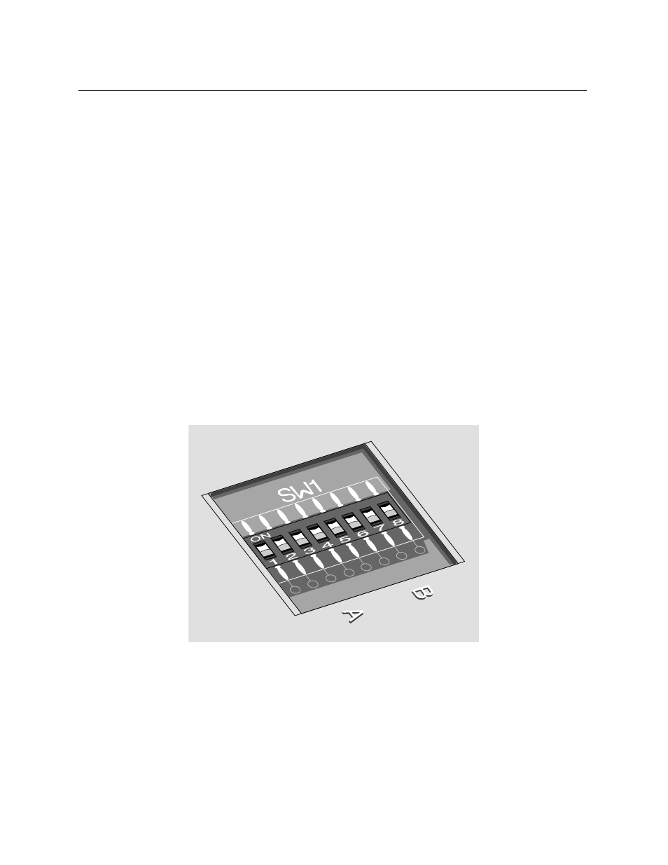
Switch Settings
The switch block is located on the bottom of the Reader. Figure 2-2 shows the switches and the
ON/OFF positions. Ensure power is off before setting the switches to ensure the switch settings
are properly loaded.
Figure 2-2. Switches
Switches 1 and 2: Table 2-1 shows the switch settings for the baud rate.
Switches 3 and 4: Table 2-2 shows the parity settings, and the other switches are described
below.