Agilent Technologies E3614A User Manual
Page 25
A-11
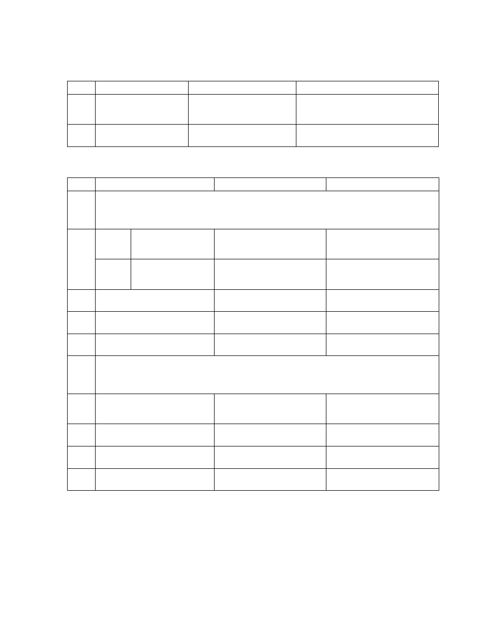
STEP
ACTION
RESPONSE
PROBABLE CAUSE
4
Check voltage from pin 13 to
pin 12 of U9.
a. Measured
voltage is positive.
b. Measured
voltage is negative.
a. Check U9A is defective.
b. Check U10 and U9D is defective.
Check R85 is open.
5
Check voltage from pin 6
to pin 5 of U9.
a. Measured
voltage is positive.
b. Measured
voltage is negative.
a. U9B is defective.
b. Check U9C is defective.
Table A-5. Low Output Voltage Troubleshooting (Cont’d)
Table A-6. Preregulator/Control Circuit Troubleshooting
STEP
MEASURE
RESPONSE
PROBABLE CAUSE
1
Set output voltage to 4.5 V +- 0.5 V for E3614A.
Set output voltage to 10 V +- 1 V for E3615A.
Set output voltage to 15 V +- 1 V for E3616A.
Set output voltage to 26 V +- 5 V for E3617A.
2
E3614A
E3615A
Waveform form from
TP6(common) to point 6
a. Normal firing pulse
b. No firing pulse
a. Check CR18, CR15, Q7, Q8
for defective.
b. Proceed to step 3.
E3616A
Voltage from TP6
(common) to point 6
a. High voltage (+0.7 V)
b. Low
voltage (0 V)
a. CR15, CR18, U2, U21
defective
b. Proceed to step 3.
3
Voltage from TP6(common) to
U4 pin 1
a. Low
voltage (-12 V)
b. High voltage (+5 V)
a. U3 defective
b. Proceed to step 4.
4
Voltage from TP6(common) to
U5 pin 1
a. High voltage (+15 V)
b. Low
voltage (-12 V)
a. U4 defective
b. Proceed to step 5.
5
Voltage from pin 6 to
pin 7 of U5
a. Measured
voltage is positive.
b. Measured
voltage is negative.
a. U5
defective
b. U6
defective
6
Set output voltage to 7 V +- 1 V for E3614A.
Set output voltage to 16 V +- 2 V for E3615A.
Set output voltage to 25 V +- 2 V for E3616A.
Set output voltage to 44 V +- 5 V for E3617A.
7
Waveform form from TP6
(common) to point 7
a. Normal firing pulse
b. No firing pulse
a. CR10, CR12, Q5, Q6
defective
b. Proceed to step 8.
8
Voltage from TP6(common)
to U4 pin 14
a. Low
voltage (-12 V)
b. High voltage (+5 V)
a. U3
defective
b. Proceed to step 9.
9
Voltage from TP6(common)
to U5 pin 14
a. High voltage (+15 V)
b. Low
voltage (-12 V)
a. U4
defective
b. Proceed to step 10.
10
Voltage from pin 8 to
pin 9 of U5
a. Measured
voltage is positive.
b. Measured
voltage is negative.
a. U5
defective
b. U6
defective