Agilent Technologies E3614A User Manual
Page 24
A-10
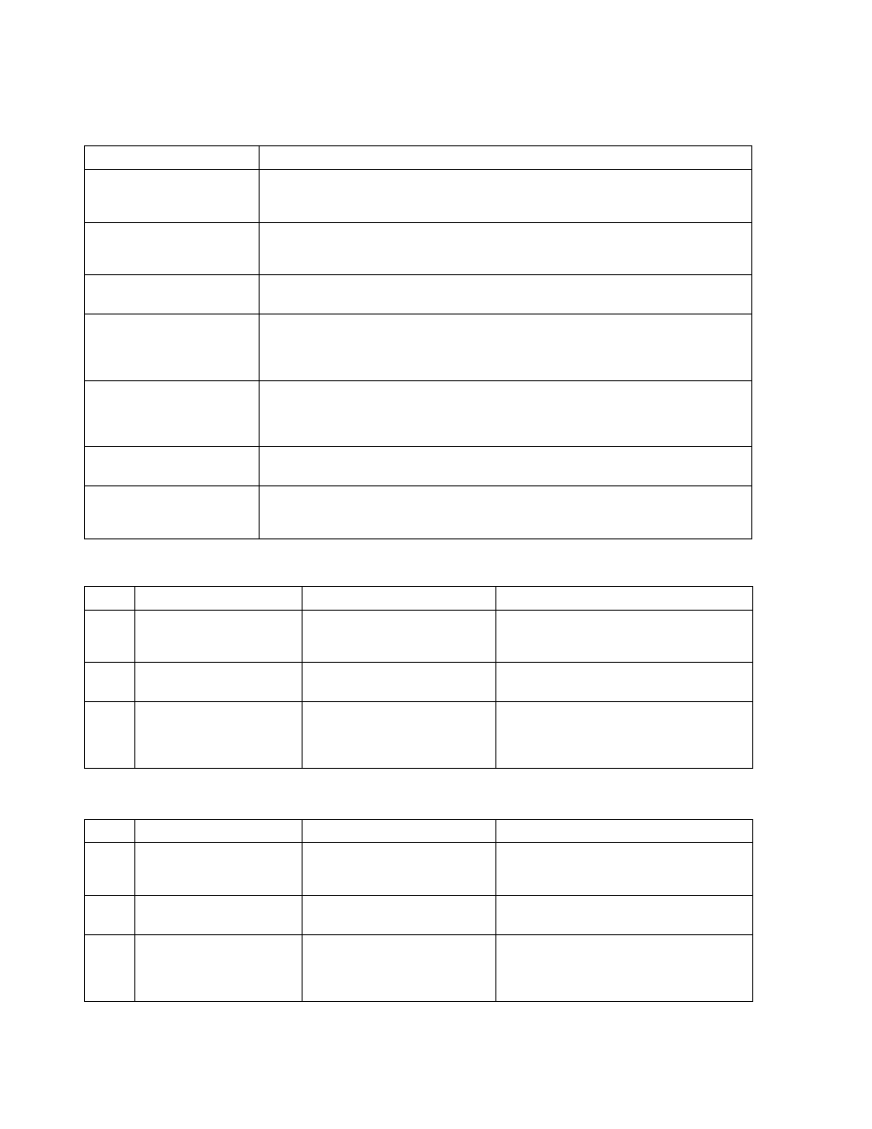
SYMPTOM
CHECKS AND PROBABLE CAUSES
Poor Load Regulation
(Constant Voltage)
a. Refer to "Measurements Techniques" paragraph.
b. Check +10 V reference voltage.
c. Ensure that the supply is not going into current limit.
Poor Load Regulation
(Constant Current)
a. Check +10 V reference voltage.
b. CR1, CR19, CR20, C2, C31 leaky.
c. Ensure that the supply is not crossing over to constant voltage operation.
Oscillates (Constant Voltage/
Constant Current)
a. Check C29 and C36 in constant voltage circuit.
b. Check C31 and C33 in constant current circuit.
Poor Stability
(Constant Voltage)
a. Check +10 V reference voltage.
b. CR27, CR28, CR23, and CR26 leaky.
c. U9
defective.
d. Noisy programming resistor R83.
Poor Stability
(Constant Current)
a. Check +10 V reference voltage.
b. CR24, CR25, CR29, and CR30 leaky.
c. U9 and U10 defective.
d. Noisy programming resistor R85.
Excessive heat
a. Check preregulator control circuit. Refer to Table A-6.
b. CR10, CR12, CR15, and CR18 short
OVP Shutdown
a. Check that the front panel OVP Adjust screw control is rotated fully clockwise.
b. Check the overvoltage protection circuit.
Refer to "Overvoltage Protection Circuit Troubles" paragraph or Table A-7.
Table A-3. Overall Troubleshooting (Cont’d)
Table A-4. High Output Voltage Troubleshooting
STEP
ACTION
RESPONSE
PROBABLE CAUSE
1
Check turn off of Q1 and
Q4 by shorting Q9 emitter
to collector.
a. Output
voltage remains high.
b. Output
voltage decreases.
a. Q1 or Q4 shorted.
b. Remove short and proceed to step 2.
2
Check turn on of Q9 by
shorting point 1 to -12 V.
a. Output
voltage remains high.
b. Output
voltage decreases.
a. Q9
open.
b. Remove short and proceed to step 3.
3
Check voltage from pin 5
to pin 6 of U9.
a. Input
voltage is positive.
b. Input
voltage is negative.
a. U9B is defective.
b. Turn down the voltage control fully
counter clockwise. Check the voltage
of U9 pin 1 is 0.
Table A-5. Low Output Voltage Troubleshooting
STEP
ACTION
RESPONSE
PROBABLE CAUSE
1
Check turn on of Q1 and
Q4 by disconnecting emitter
of Q9.
a. Output
voltage remains low.
b. Output
voltage increases.
a. Q1 or Q4 open.
b. Reconnect emitter lead and proceed to step 2.
2
Check turn off of Q9 by
shorting point 1 to +15 V.
a. Output
voltage remains low.
b. Output
voltage increases.
a. Q9
shorted.
b. Remove short and proceed to step 3.
3
Eliminate constant current
comparator as a source of
trouble by disconnecting
anode of CR22.
a. Output
voltage is increases.
b. Output
voltage remains low.
a. Proceed to step 4.
b. Reconnect lead and proceed to step 5.