Agilent Technologies E3614A User Manual
Page 23
A-9
After the trouble has been isolated to one of the feedback
loops, troubleshooting can proceed as described in Tables A-
4, A-5, or A-6.
Series Regulating Feedback Loop. When troubleshooting
the series regulating loop, it is useful to open the loop since
measurements made anywhere within a closed loop may
appear abnormal. With a loop closed, it is very difficult to sep-
arate cause from effect. As described in Tables A-4 and A-5,
the conduction or cutoff capability of each stage is checked
by shorting or opening a previous stage, as follows:
1.
Shorting the emitter to collector of a transistor simu-
lates saturation, or the full ON condition.
2.
Shorting the emitter to base of a transistor cuts it off,
and simulates an open circuit between emitter and
collector.
Although a logical first choice might be to break the loop
somewhere near its mid-point, and then perform successive
subdividing tests, it is more useful to trace the loop from the
series regulator backwards a stage at a time, since loop fail-
ures occur more often at the higher power levels.
Preregulator Feedback Loop. The preregulator feedback
loop (SCR control circuit) can be conveniently checked using
Table A-6. As indicated in Table A-6, the control circuit is
checked by starting with the waveform at point 7 and point 6
(shown on the schematic diagram) and tracing forwards and
backwards from this point.
Overvoltage Protection Circuit Troubles
When troubleshooting the overvoltage protection circuit, it is
useful to check the turn-on overshoot control circuit which
includes U20 and Q10. The function of the control circuit is to
slow down the rising speed of the +15 V bias the moment the
power is turned on. This function prevents the supply from
false OVP tripping the moment the power is turned on. After
the troubles has been isolated to overvoltage protection cir-
cuit, troubleshooting can proceed as described in Table A-7.
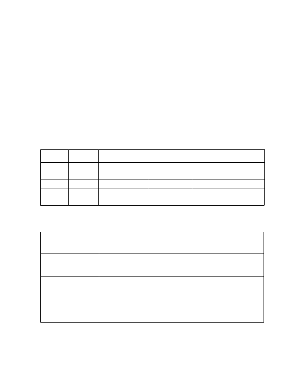
Table A-2. Reference and Bias Circuit Troubleshooting
METER
COMMON
METER
POSITIVE
NORMAL INDICATION
NORMAL RIPPLE
(p-p)
PROBABLE CAUSE
TP6
point 2
+15.0 +/- 0.3 Vdc
2 mV
Check U13, CR31, and CR32.
TP6
point 4
-12.0 +/- 0.3 Vdc
2 mV
Check +15 V bias or U14.
TP6
TP7
+10.5 +/- 0.2 Vdc
2 mV
Check +15 V bias, U11, and U14.
TP6
point 3
-5.1 +/- 0.5 Vdc
2 mV
Check -12 V bias or VR1.
TP6
point 5
+5.0 +/- 0.3 Vdc
4 mV
Check U1 and CR2.
Table A-3. Overall Troubleshooting
SYMPTOM
CHECKS AND PROBABLE CAUSES
High Output Voltage
a. Check series regulator feedback loop or preregulator feedback loop.
b. Refer to "Regulating Loop Troubles" paragraph or Table A-4 or A-6 as instructed.
Low and No Output Voltage
a. If output is zero, check fuse.
b. Check series regulator feedback loop or preregulator loop.
Refer to "Regulating Loop Troubles" paragraph or Table A-5 or A-6 as instructed.
c. Check CR20 shorted.
High Ripple
a. Check operating setup for ground loops.
b. If output floating, connect 1
µ
F capacitor between output and ground.
c.
Ensure that the supply is not crossing over to constant current mode
under loaded conditions.
d. Check for low voltage across C7 or Q1 and Q4.
e. Check for excessive ripple on reference voltages (Table A-2).
Poor Line Regulation
(Constant Voltage)
a. Check +10 V reference voltage.
b. Check U9.