Auto-tracking operaton – Agilent Technologies E3614A User Manual
Page 13
1-13
Remote Sensing. To remote sense with auto-series operation,
set SENSE switch of the master unit and set SENSE switch of the
slave unit to remote.
Remote Analog Voltage Programming. To remote analog pro-
gram with auto-series operation, connect program (external) volt-
ages to the "CV" or "CC"" terminal of the master unit and set "CV"
or "CC" switch of the master unit to remote.
AUTO-TRACKING OPERATON
Auto-tracking operation of power supplies is similar to auto-series
operation except that the master and slave supplies have the
same output polarity with respect to a common bus or ground.
This operation is useful where simultaneous turn-up, turn-down or
proportional control of all power supplies is required.
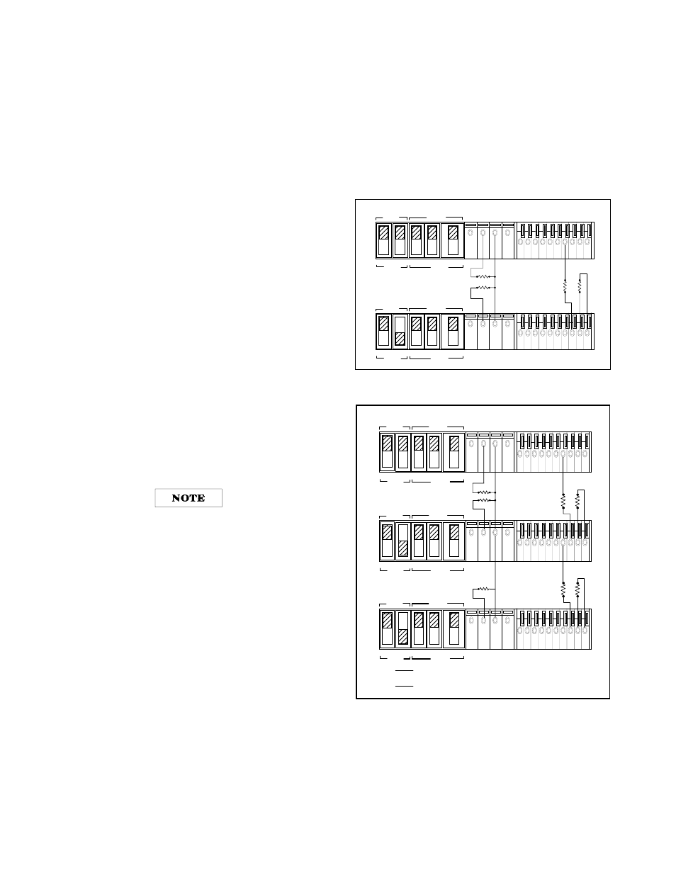
Figure 14 and Figure 15 show two and three supplies connected
in auto-tracking with their negative output terminals connected
together as a common or ground point. For two units in auto-
tracking a fraction R2/(R1+R2) of the output of the master supply
is provided as one of the inputs to the comparison amplifier of the
slave supply, thus controlling the slave's output. The master sup-
ply in an auto-tracking operation must be the positive supply hav-
ing the largest output voltage. Turn-up and turn-down of the
power supplies are controlled by the master supply. In order to
maintain the temperature coefficient and stability specifications of
the power supply, the external resistor should be stable, low
noise, low temperature.
Determining Resistors. External resistors control the fraction of
the master unit's voltage that is supplied from the slave unit. For
two units in auto-tracking the ratio R1 and R2 is
R2/(R1+R2 = (Vs/Vm)
Where Vm = master output voltage
Vs = slave output voltage
It is recommended to connect a 0.1
µ
F capacitor in paral-
lel with R2 in two supplies operation or R2 and R4 in
three supplies operation to ensure the stable operation.
Setting Voltage and Current. Use the master unit's VOLTAGE con-
trol to set the output voltage from both units. When the master is in
CV operation, the master's output voltage(Vm) is the same as its
voltage setting, and the slave's output voltage for two units operation
is Vm(R2/(R1+R2)). The VOLTAGE control of the slave unit is dis-
abled. Set the CURRENT controls of master and slave units above
the required currents to assure CV operation of master and slave
units.
Overvoltage Protection. Set the OVP shutdown voltage in each
unit so that it shuts down at a voltage higher than its output volt-
age during auto-tracking operation. When a master unit shuts
down, it programs any slave units to zero output. When a slave
unit shuts down, it shuts down only itself.
Remote Sensing. To include remote sensing with auto-tracking
operation independently, set up each unit for remote sensing
according to the remote-sensing instructions under previous
paragraph.
Remote Analog Programming.
To simultaneously remote pro-
gram both units' output voltages, set up only the master unit for
remote voltage programming according to the remote program-
ming instructions. To vary the fraction of the output voltage contri-
bution by the slave unit, connect a variable resistor in place of R2
in two units operation. To independently remote program each
unit's output current setting, set up each unit for remote control of
output current according to the instructions under "Remote Pro-
gramming, Constant Current" paragraph.
Figure 14. Auto-Tracking Operation of Two Supplies
Figure 15. Auto-Tracking Operation of Three Supplies
MASTER
SLAVE
CV
CC
SENSE
LOCAL
REMOTE
OUT
+S
-S
+
_
CV
CC VREF A1 A2 A3 A4 A5
+
+
M/S 1
M/S 2
_
_
MASTER
SLAVE
CV
CC
SENSE
LOCAL
REMOTE
OUT
+S
-S
+
_
CV
CC VREF A1 A2 A3 A4 A5
+
+
M/S 1
M/S 2
_
_
MASTER POWER SUPPLY
SLAVE POWER SUPPLY
R1
R2
LOAD
LOAD
MASTER
SLAVE
CV
CC
SENSE
LOCAL
REMOTE
OUT
+S
-S
+
_
CV
CC VREF A1 A2 A3 A4 A5
+
+
M/S 1
M/S 2
_
_
MASTER POWER SUPPLY
MASTER
SLAVE
CV
CC
SENSE
LOCAL
REMOTE
OUT
+S
-S
+
_
CV
CC VREF A1 A2 A3 A4 A5
+
+
M/S 1
M/S 2
_
_
SLAVE POWER SUPPLY(S1)
MASTER
SLAVE
CV
CC
SENSE
LOCAL
REMOTE
OUT
+S
-S
+
_
CV
CC VREF A1 A2 A3 A4 A5
+
+
M/S 1
M/S 2
_
_
SLAVE POWER SUPPLY(S2)
R1
R2
R3
R4
Vs1 =
R2
R1+ R2
Vm
Where Vm = masters unit's output voltage
Vs1 = slave(S1) unit's output voltage
Vs2 = slave(S2) unit's output voltage
LOAD
LOAD
LOAD
Vs2 =
R4
R3+ R4
Vs1