Connecting wires to terminals – Kenwood KIV-700 User Manual
Page 12
1
2
3
4
5
6
7
8
1
2
3
4
5
6
7
8
iP
od
A
UDIO IN
iP
od
VIDEO IN
iPod
VIDEO OUT
iPod
AUDIO OUT
12 | Quick Start Guide
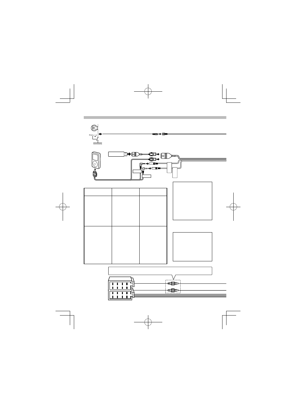
Connecting Wires to Terminals
⁄
See
Ignition wire (Red)
Battery wire (Yellow)
A–7 Pin (Red)
A–4 Pin (Yellow)
Connector A
Connector B
Connector Function Guide
Pin Numbers for
ISO Connectors
Cable Colour
Functions
External Power
Connector
A-4
Yellow
Battery
A-5
Blue/White
Power Control
A-6
Orange/White
Dimmer
A-7
Red
Ignition (ACC)
A-8
Black
Earth (Ground)
Connection
Speaker
Connector
B-1
Purple
Rear Right (+)
B-2
Purple/Black
Rear Right (–)
B-3
Gray
Front Right (+)
B-4
Gray/Black
Front Right (–)
B-5
White
Front Left (+)
B-6
White/Black
Front Left (–)
B-7
Green
Rear Left (+)
B-8
Green/Black
Rear Left (–)
⁄
• Speaker Impedance
: 4 – 8 Ω
• USB terminal Maximum
Supply current
: 500 mA
⁄
Do not remove the cap
when you do not use the
USB cable. The connector
will cause the unit to
malfunction if it gets in
touch with any metallic
part of the vehicle.
For the sake of safety, be sure to connect the parking sensor.
⁄
Connect to the vehicle’s parking brake detection switch harness.
Parking sensor wire (Light Green)
Parking sensor wire Junction cable
(Light Green) (Accessory
3)
USB connector (1m)
iPod cable
(Accessory
4)
iPod
(commercially
available)
USB device (commercially available)
B59-2017-00_00_E.indb 12
B59-2017-00_00_E.indb 12
10/03/24 9:31
10/03/24 9:31