Installation – APC BC300 Series User Manual
Page 17
Installation
990-1401
Installation Guide APC BC300 Series 40kW 208/450/480V UPS
17
Notes:
1. 3- or 4-wire provided source.
2. Cables not provided by APC.
3. Recommended input over-current protection (MIB) based on an 80% rated device.
4. All AC cables must be AC 3- or 4-wire 3-phase.
5. Keep UPS input, output and control cables in separate conduits.
6. Installation must comply with all applicable national and local codes.
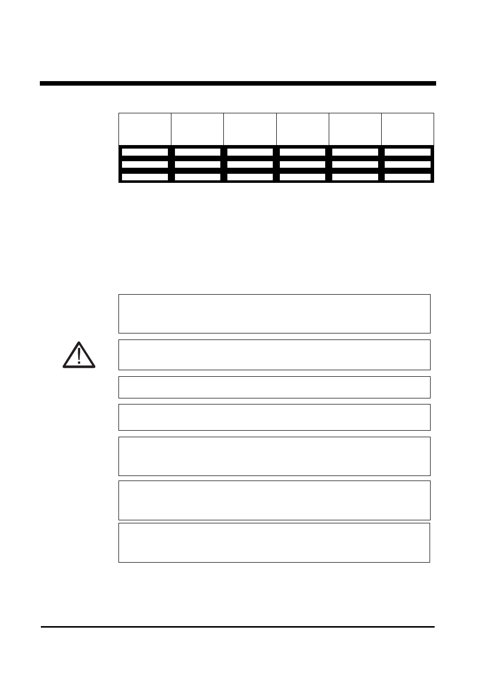
UPS Model
Input
Current
Output
Current
Recom-
mended
MIB
DC Voltage
DC Current
40kW 208V
161A
111A
200AT
216V
200A
40 kW 450V
75A
51A
95AT
216V
200A
40kW 480V
69A
48A
130AT
216V
200A
NOTICE!
Over-current protection and UPS input AC disconnect means must be provided.
See the “Technical Specifications” section in this Installation Guide for recommended UPS input
and output over-current protection.
CAUTION!
UPS systems can be connected as 3-phase, a 3-wire plus ground, provided that the load is not
connected to the neutral conductor.
NOTICE!
Only authorized electricians may install the UPS and all applicable codes must be observed.
NOTICE!
Always keep AC, DC and communication cables separated.
NOTICE!
The grounding electrode conductor (Protective Earth - PE) must be the same size (ampacity) as
the UPS input circuit conductors. Conduit is not an acceptable grounding electrode conductor -
see National Electrical Code Section 250-91(a).
NOTICE!
The unit is wired from the factory as a separately derived system. Output neutral is bonded to
equipment ground through main bonding jumper inside the UPS. See National Electrical Code
Article 250-5(d) and 250-26 for correct installation grounding.
NOTICE!
The maintenance bypass switch must be a 4-pole device switching all three phases and neutral.
If you are using a 3-pole device, contact APC Technical Support for instructions on how to
convert the unit to a not-separately derived system.