Physical description, User interface, Closed-loop valve controller – High Country Tek DRF Series User Manual
Page 6
021-DRF Rev A
DRF User Manual
6
Copyright © High Country Tek, Inc.
– 2013
DRF
Closed-loop Valve Controller
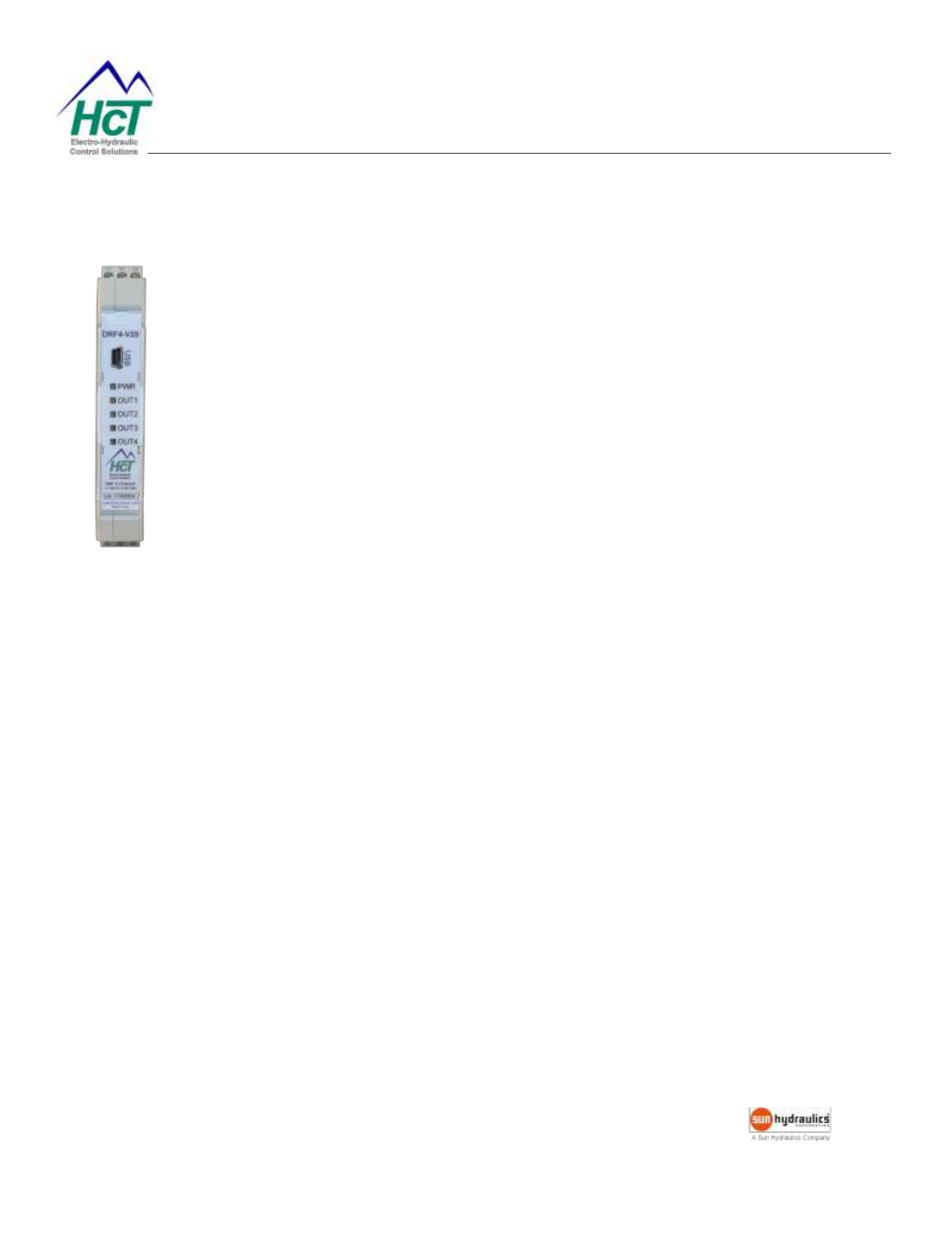
Physical Description
There are PWR LED and OUTx LEDs. For DRF-4, there are 5 LEDs. The PWR LED is
green when the applied voltage is within the operating range.
OUTx LEDs indicate current output for a given channel. The LEDs are yellow
and the
brightness will vary with the output current.
In the case of a fault the LEDs will flash red with a flash code. See Fault Status for
details.
The DRF communicates with the Graphical User Interface through the USB port.
When connected to a PC, the DR controller is recognized as a USB device with or
without power supply. However, it must be powered when configuring the settings.
User Interface
The DRF has a number of internal settings.
Users can open the Graphical User Interface to view, make changes and save the settings in a data file which can
be uploaded to any DRF controller.
The Hand Held Interface can also be used to view and make changes, but this device does not have the capability
to save the settings in a data file. The programmer, cable and adapter are self-contained which makes the HHI a
viable alternative for field work.