Double/single/single solenoid control (drf4-vxx), Drf4, Closed-loop valve controller – High Country Tek DRF Series User Manual
Page 21
021-DRF Rev A
DRF User Manual
21
Copyright © High Country Tek, Inc.
– 2013
DRF
Closed-loop Valve Controller
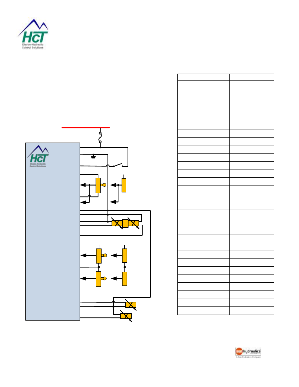
Double/Single/Single Solenoid Control (DRF4-Vxx)
The DRF drives a dual-coil valve with joystick input J5-1 and 2
single-coil valves with joystick input J6-1 and J6-3.
Set the dither and output settings according to the valve
specifications.
Schematic
FUSE
+V Power Input
9 - 32VDC
+V = Enabled
PWR J1-1
DRF4
Electronic Valve
Controller
Enable J1-3
GND J1-2
-10V Ref. Out J4-1
+10VDC @ 20mA
0-10VDC
+10V Ref. Out J4-3
Ch. 1 I/P J5-1
V
D
C
I/
P
m
A
I/
P
Supply Voltage
4-12mA
Ch. 2 I/P J5-3
+10VDC @ 20mA
0-10VDC
Ch. 3 I/P J6-1
Sig GND J6-2
V
D
C
I/
P
m
A
I/
P
Supply Voltage
4-20mA
Ch. 4 I/P J6-3
Prop. PWM (Sourcing)
Ch. 3 Out J3-1
Sig GND J3-2
Ch. 4 Out J3-3
Prop. PWM (Sourcing)
+10VDC @ 20mA
0-10VDC
V
D
C
I/
P
m
A
I/
P
4-20mA
Supply Voltage
Sig GND J4-2
J5-2
Prop. PWM (Sourcing)
Ch. 2 Out J2-3
Prop. PWM (Sourcing)
Ch. 1 Out J2-1
Sig GND J2-2
0 to -10VDC
12-20mA
Example Settings
Parameter
Value
C1 Mode
2 CUR USE ENBL
C1 Min input
0.2 V
C1 Max input
10.0 V
C1 Min output
5 mA
C1 Max output
600 mA
C1 Ramp up
1 S
C1 Ramp down
1 S
C2 Mode
4 IN1 USE ENBL
C2 Min input
-0.2 V
C2 Max input
-10.0 V
C2 Min output
5 mA
C2 Max output
600 mA
C2 Ramp up
0 S (NOT USED)
C2 Ramp down
0 S (NOT USED)
C3 Mode
2 CUR USE ENBL
C3 Min input
0.2 V
C3 Max input
10.0 V
C3 Min output
5 mA
C3 Max output
600 mA
C3 Ramp up
1 S
C3 Ramp down
1 S
C4 Mode
2 IN4 USE ENBL
C4 Min input
0.2 V
C4 Max input
10.0 V
C4 Min output
5 mA
C4 Max output
600 mA
C4 Ramp up
1 S
C4 Ramp down
1 S
Dither frequency
150 Hz.