Open loop double solenoid control (drc2-vxx), Valve controller, Drc2 – High Country Tek DRC Series User Manual
Page 17
021-DRC Rev A
DRC User Manual
17
Copyright © High Country Tek, Inc.
– 2013
DRC
Valve Controller
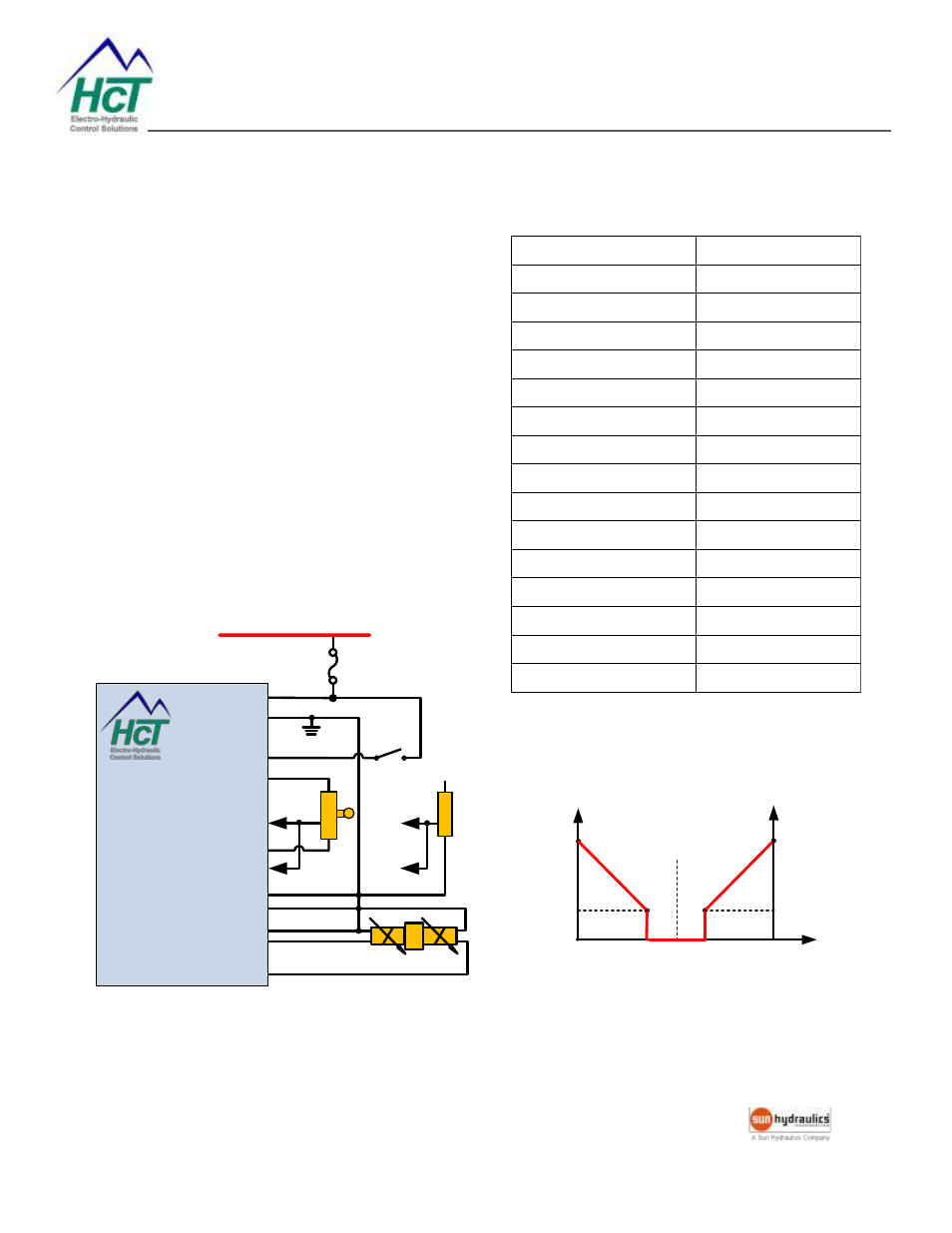
Open Loop Double Solenoid Control (DRC2-Vxx)
The DRC can drive a double solenoid valve with a
joystick or potentiometer of
10kΩ.
If enable switch is not used, set channel 1 to be Mode
1, channel 2 to be Mode 3.
If enable switch is used, set channel 1 to be Mode 2,
channel 2 to be Mode 3.
The minimum and maximum input parameters for the
two channels should not be overlap.
Set the dither and output settings according to the
valve specifications.
Schematic
FUSE
+V Power Input
9 - 32VDC
+V = Enabled
PWR J1-1
DRC2
Electronic Valve
Controller
Enable J1-3
GND J1-2
-10V Ref. Out J4-1
+10VDC @ 20mA
0 to 10VDC
+10V Ref. Out J4-3
Ch. 1 I/P J5-1
Sig GND J4-2
J5-2
V
D
C
I/
P
m
A
I/
P
Supply Voltage
4-20mA
Ch. 2 I/P J5-3
Prop. PWM (Sourcing)
Sig GND J2-2
Ch. 1 Out J2-1
Ch. 2 Out J2-3
Prop. PWM (Sourcing)
0 to -10VDC
Example Settings
Input / Output Diagram
-10V
(Ch. #2)
600mA
5mA
600mA
5mA
Center (0V)
Ch.
#2
Current
Ch.
#1
Current
10V
(Ch. #1)
Command
Input
-0.2V
(Ch. #2)
0.2V
(Ch. #1)
Parameter
Value
C1 Mode
2 IN1 USE ENBL
C1 Min input
0.2 V
C1 Max input
10.0 V
C1 Min output
5 mA
C1 Max output
600 mA
C1 Ramp up
1 S
C1 Ramp down
1 S
C2 Mode
3 IN1 FOLLOWER
C2 Min input
-0.2 V
C2 Max input
-10.0 V
C2 Min output
5 mA
C2 Max output
600 mA
C2 Ramp up
0 S (NOT USED)
C2 Ramp down
0 S (NOT USED)
Dither frequency
150 Hz.