Character layout, Wiring connections, Figure 4: character layout – High Country Tek DVC61 User Manual
Page 9: Figure 5: connector pin diagram, Table 1: pin assignments, High country tek
High Country Tek
•
Electronic Solutions for Industry
March 28, 2007
© Copyright 2003, High Country Tek Company
All rights reserved. Contents subject to Change
9
Character Layout
character height 9.22mm x 4.84mm
1
2
3
4
5
6
7
8
9
10
11
12
13
14
15
16
17
18
19
20
(actual size)
Figure 4: Character Layout
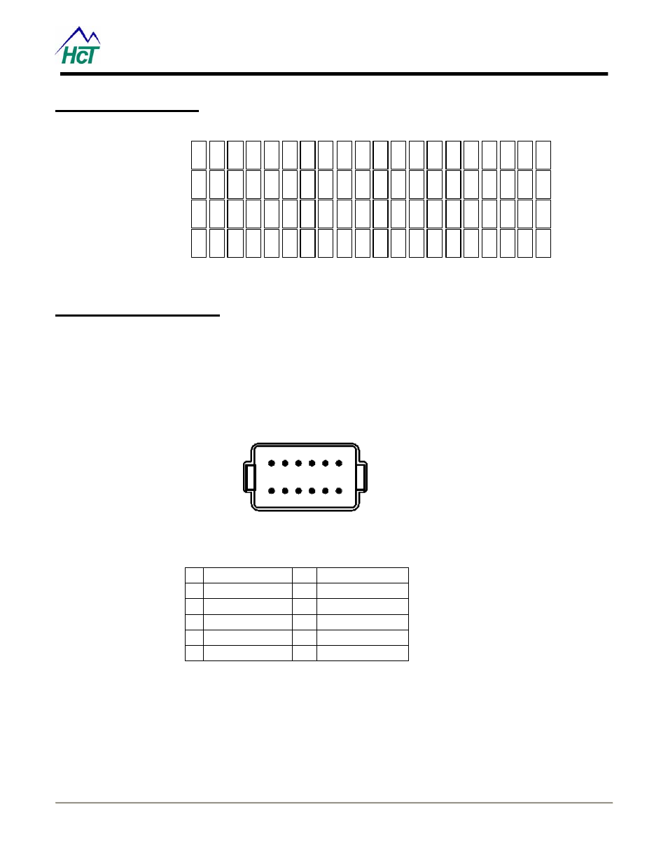
Wiring Connections
• 12 pin Deutsch # DT15-12PA
connector designed for severe
under – hood environments
• Accepts 14 AWG through 18
AWG wire
1
2
3
4
5
6
12
11
10
9
8
7
DT15-12PA
Figure 5: Connector Pin Diagram
1 INPUT 1A/1B
7
RS-232 (TXD)
2 INPUT 2A/2B
8
RS-232 (RXD)
3 +PWR
9 GROUND
4 GROUND
10
INPUT
3A/3B
5 CANH
11
INPUT
4A/4B
6 CANL
12
INPUT
5A/5B
Table 1: Pin Assignments
*Note: See the Accessories section for mating connector information.