Hawkeye Tank Preparation User Manual
Page 3
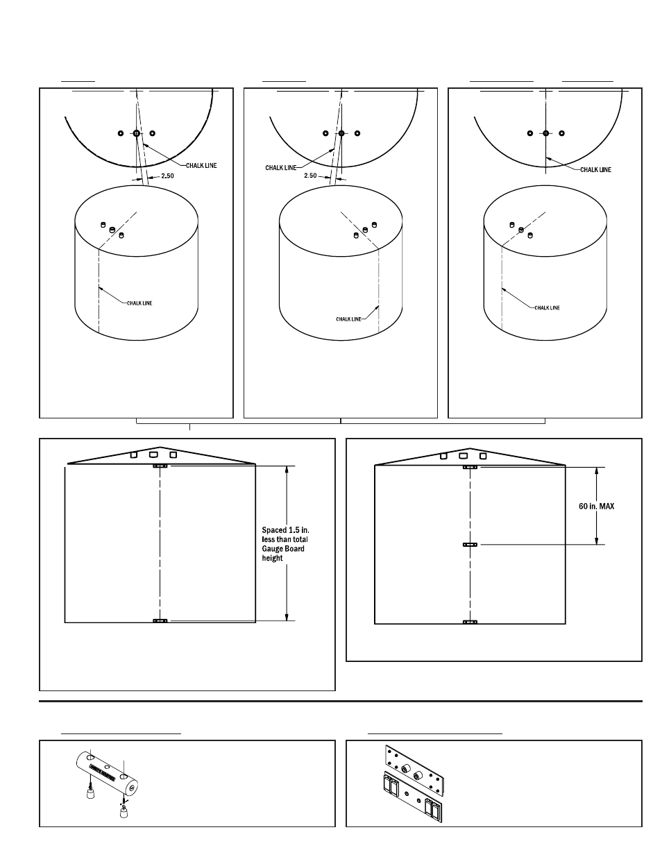
Run the chalk line from the centre of the tank
roof to the ground. Looking towards the cen-
tre of the tank from the edge, position the chalk
line 2.5 in to the RIGHT of the Gauge Head
Mount. Snap the line.
►
C1.) Redtail
D1.) Float Guide Cable Anchor
D2.) Magnetic Gauge Board Clips
C3.) Sparrowhawk , and Model 750
C2.)Roadside
Please note that the preparation procedures differ for different gauge heads systems. Please ensure you use the proper procedure for
your gauge head.
1.)
Run the chalk line from the centre of the tank
roof to the ground through the centre of the
Gauge Head Mount. Snap the line.
1.)
Run the chalk line from the centre of the tank
roof to the ground. Looking towards the cen-
tre of the tank from the edge, position the chalk
line 2.5 in to the LEFT of the Gauge Head
Mount. Snap the line.
1.)
C.) Preparing the Tank for a Gauge Board
Weld the top and bottom gauge board clips, centred on the chalk line, to
the wall of the tank . The vertical distance between centres of the top and
bottom gauge board clips shall be 1.5 in less than the overall length of the
gauge board. See section D for No-Weld Alternative to gauge board clips.
A Hawkeye Industries Inc. Poly Float
Guide Anchor can be lowered into the
tank to anchor the float guides if it is
in service or otherwise inaccessible.
Consult the Float Guide Kit installation
instructions for details.
Magnetic gauge board clips can be
substituted for weld-on clips if welding
is not suitable. Follow the same pro-
cedures for spacing as with weld-on
clips.
Weld intermediate clips between the top and bottom clips, ensuring the
span between the clip centres does not exceed 5 ft (60 in).
2.)
3.)
Tank Preparation Complete.
►
D.) No Weld Alternatives
Tank Preparation Instructions, April 2010
3