Hawkeye Cam Lock Connections User Manual
Cam lock connections, Gauge side preparation installation, Requirements
This document contains the recommended procedures using an optional Cam Lock connection with a Hawkeye Gauge Head.
Gauge Side Preparation
Installation
Installation Instructions
Cam Lock Connections
Cam Lock Installation Instructions,November 2011
1
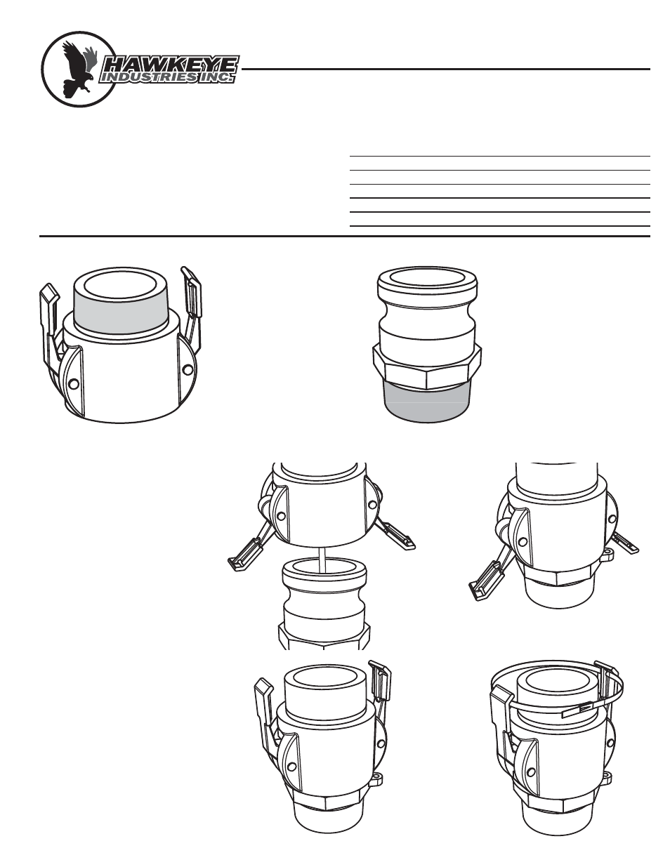
1.)
The Female Cam Lock
(Type B or D, depending
on Gauge Head) is in-
stalled on the gauge head
side of the connection.
2.)
Lubricate the the threads
(figure 1)
3.)
Thread the coupling onto
the gauge head, and
tighten to wrench tight.
1.)
Run the float cable from the
indicator, through both parts
of the cam lock connection,
and into the tank.
Connect the float per gauge
installation instructions.
2.)
Open the female cam lock
handles, and align the con-
nection components (Figure
3).
3.)
Drop the female connection
over the male (Figure 4) and
rotate the gauge head for
proper alignment to the
gauge board.
4.)
Close the female cam lock
handles once the gauge
head rotation is set (Figure 5)
5.)
Secure the handles in the
closed position by running
the enclosed stainless zip tie
through the holes in the han-
dles, and cinching it down
tightly (Figure 6)
► Pipe Wrench
► Thread Sealant
Requirements
Ensure the tank is prepared to recieve a level gauging system.
This procedure forms part of the gauge head installation.
Tools
Parts Required
QTY
Part
►
1
Gauge Head
►
1
CamLock Connector Kit, which includes:
1
CamLock Connector - Female (Type B or D
1
CamLock Connector - Male (Type A or F)
1
Lockout Device
Figure 2
Figure 1
Figure 3
Figure 4
Figure 5
Figure 6
TANK PREPARATION | GAUGE BOARD KIT INSTALLATION | FLOAT GUIDE KIT INSTALLATION |
GAUGE HEAD INSTALLATION
| GOSHAWK INSTALLATION
Tank Side Preparation
1.)
The Male Cam Lock (Type A
or F, depending on tank
nozzle) is installed on the
tank side of the connection.
2.)
Lubricate the the threads
(figure 2)
3.)
Thread the coupling onto
the tank, and tighten to
wrench tight.