Hawkeye Tank Preparation User Manual
Page 2
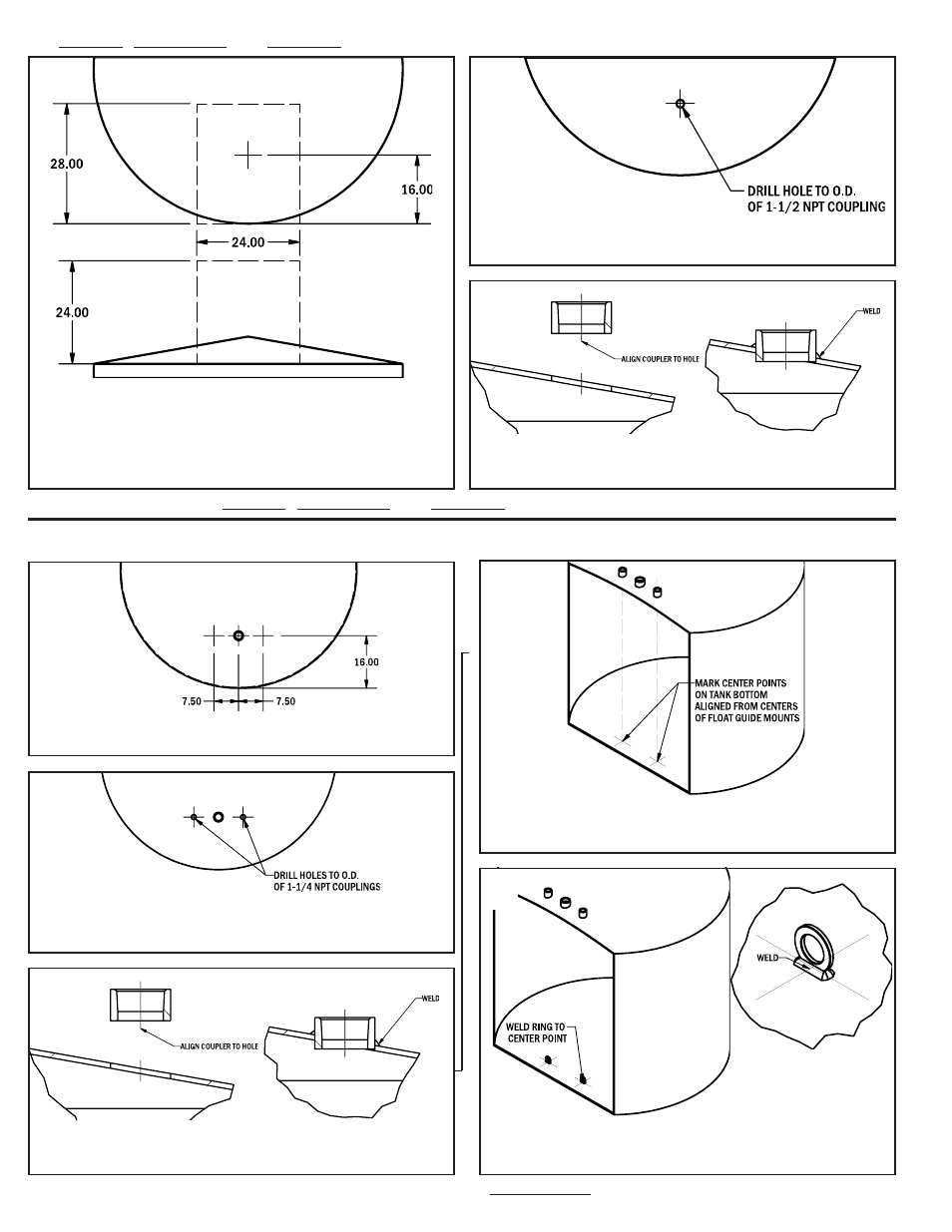
Mark a location on the top of the tank for the gauge head connection. The
connection shall be 16 in. from the tank wall, with clearance of 3 ft above,
and 1 ft to each side of the gauge head. Ensure a clear path, free of ob-
structions, on the outside of the tank leading from the gauge head mount
to the ground.
Cut a hole to match the diameter of the coupling at the marked location.
Align the1-1/2 NPT coupling to the cut hole and weld to the tank roof
using appropriate weld procedures.
1.)
2.)
3.)
►
►
►►
►
Mark two locations, 7.5 in on either side of the gauge head mount.
Cut a hole to match the diameter of the 1-1/4 couplings at the marked lo-
cations.
Align a 1-1/4 NPT coupling to each cut hole and weld to the tank roof
using appropriate weld procedures.
Suspend plumb bob from centre of float guide mount (1-1/4 NPT cou-
pling) to tank floor.
At the plumb location on the tank floor, weld the float guide anchor ring.
See section D for No-Weld alternative to float guide anchors
1.)
2.)
3.)
4.)
5.)
A2.) Roadside , Sparrowhawk , and Model 750 Gauge Head
Roadside , Sparrowhawk , and Model 750 Gauge Head Preparation Complete, proceed to section B.
Float Guide Kit Preparation Complete, proceed to section C.
B.) Preparing the Tank for a Float Guide Kit
►
Hawkeye Industries Inc.
2