AMETEK 1025 Foot & Palm Switches User Manual
Page 16
Chapter 3: Operating Instructions
Operating Manual
12
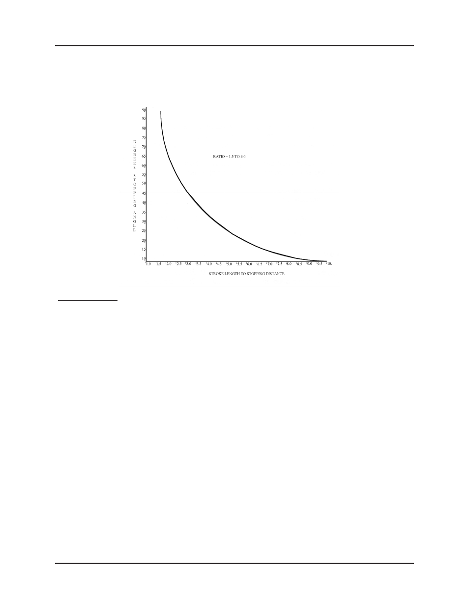
9.
Determine the ratio of press stroke to stopping distance (divide stroke by
stopping distance). Locate this ratio on the horizontal axis of the graph, move
up to the curve and read across to the vertical axis, fi nding the stopping angle
in degrees.
Review Points:
1.
Be sure to start at exactly 90 degrees or 270 degrees by observing crankshaft
or indicator.
2.
Be sure press does not go through bottom or top of stroke.
3.
Small differences in stopping distance make for large differences in stopping
angle, especially when the stopping angle exceeds 45 degrees. Read the CSP
dial carefully.
When determining stop angle be sure of the following:
1.
The P/V transducer cable must be parallel to the slide motion. The cable
magnet must be directly above the P/V transducer.
2.
In down stroke tests, the ram must stop before it reaches the bottom of the
stroke.
3.
The mid-stroke position can be used as the 90 degree crankshaft position.
Since this is one of the reference points used to make linear measurements of
the ram travel to determine stop angle, care must be taken to initiate the stop
at exactly the 90 degree position.
4.
If the press is equipped with a functioning angular position indicator, this can
be used to indicate crank or cam angular position. If no indicator is available,
the angular position may be determined from the crank or camshaft position.
Mark the 90 degree position.