Chapter 4: expansion modules – AMETEK 1995L Micro-Set PLS User Manual
Page 18
Chapter 4: Expansion Modules
Installation and Maintenance Manual
14
Chapter 4: Expansion Modules
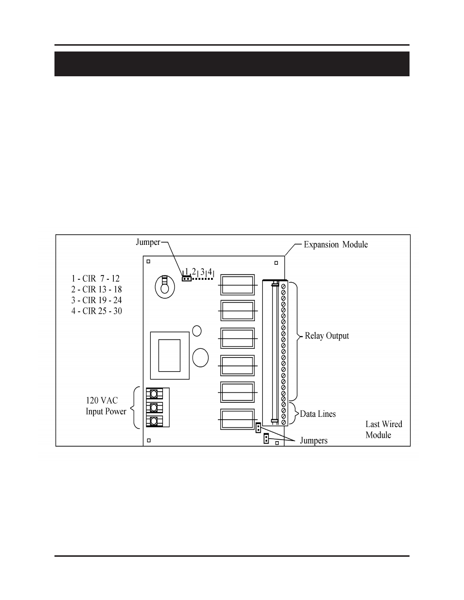
The 1995L PLS provides six outputs. A 1995E Expansion Module is required for each additional six
outputs desired, up to a total of 30 outputs, or four expansion modules. The circuit location of each
expansion module is defined by the location of a two-pin jumper on an eight-pin block in the upper left
corner of the module. This jumper must be installed for the expansion module to operate. Two pairs of
pins, located in the lower right corner of the expansion module, should be jumpered on only the last
module in the wiring group. See Fig. 10-4 (Chapter 10: Wiring Diagrams) for additional expansion
module wiring information. Each expansion module is provided with a full set of terminal strip designa-
tion decals. To avoid confusion, the appropriate decals should be installed along the output terminals,
based on the location of the output selection jumper outlined below.
Fig. 4-1
See Section 3.5: Selecting Number of Outputs, for instructions on how to program unit for use with
expansion modules.