AMETEK 1746 LDT Interface Card User Manual
Page 19
Chapter 4: Application Examples
Installation & Programming Manual
16
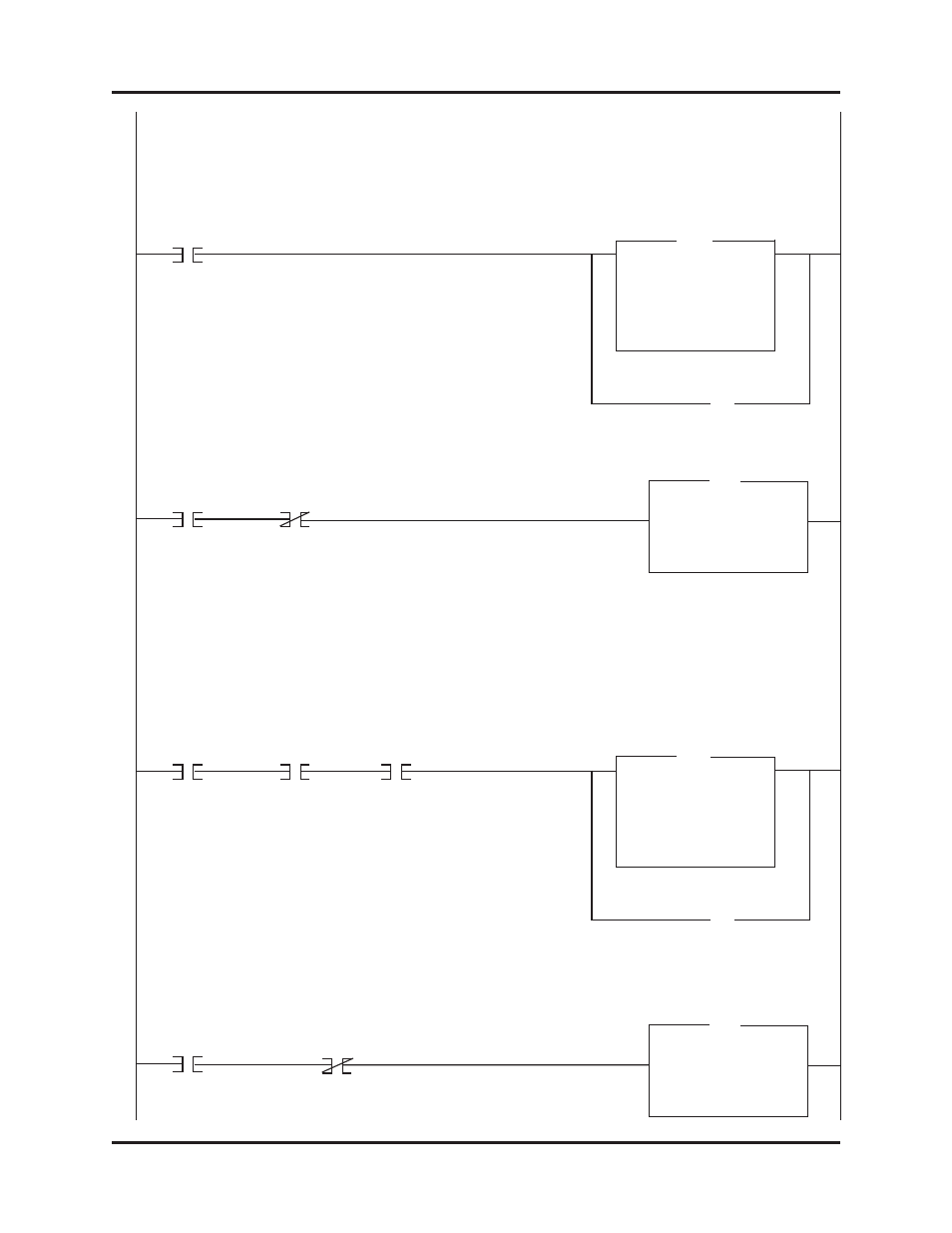
On the first scan, the start 1746R configuration flag is set. When this flag is set, the configuration command is
copied into the output image table with the programming bit set. This will continue until the command has been
acknowledged in the input image table.
0000
First Pass
S2:1
MOV
Move
Source
1
1<
Dest
N10:0
0 <
Clear Program Bit
O:1
( U )
15
OTHER
CLEAR STATE FLAGS AND SET UP FOR INITIALIZATION
COP
Copy File
Source #N7:0
Dest
#O:1.0
Length 8
0001
COPY COMMAND TO CONFIGURE THE 1746R CARD
Config Bit Set
N10:0
Ack Bit Cleared
I:1
15
0
15
OTHER
When the 1746R configuration command is complete, the program will copy the position scaling command for
resolver 1 into the output image table with the programming bit set. This command will configure resolver 1 for
a total scale factor of 1000 and turn count of 10. This will configure the resolver for 100 counts per turn. This
continues until the command has been acknowledged.
0002
WHEN COPY OF THE 1746R CONFIGURATION COMMAND IS COMPLETE, SET THE STATE FLAG TO
CONFIGURE RESOLVER 1
Config Bit Set
N10:0
Ack Bit Set
I:1
0
15
OTHER
Program Bit Set
O:1
15
OTHER
MOV
Move
Source
2
2 <
Dest
N10:0
0 <
Clear Program Bit
O:1
( U )
15
OTHER
COP
Copy File
Source #N7:10
Dest
#O:1.0
Length 8
0003
COPY THE COMMAND TO CONFIGURE RESOLVER 1 WITH SCALE FACTOR AND TURNS COUNTING
INFORMATION
Res 1 Config Bit Set
N10:0
Ack Bit Cleared
I:1
1
15
OTHER