Communication format, Start bit and data bits, Parity bit – Red Lion PAXCDC1,2 (RS232/RS485) User Manual
Page 6: Stop bit
6
Communication Format
Data is transferred from the meter through a serial communication channel.
In serial communications, the voltage is switched between a high and low level
at a predetermined rate (baud rate) using ASCII encoding. The receiving device
reads the voltage levels at the same intervals and then translates the switched
levels back to a character.
The voltage level conventions depend on the interface standard. The table
lists the voltage levels for each standard.
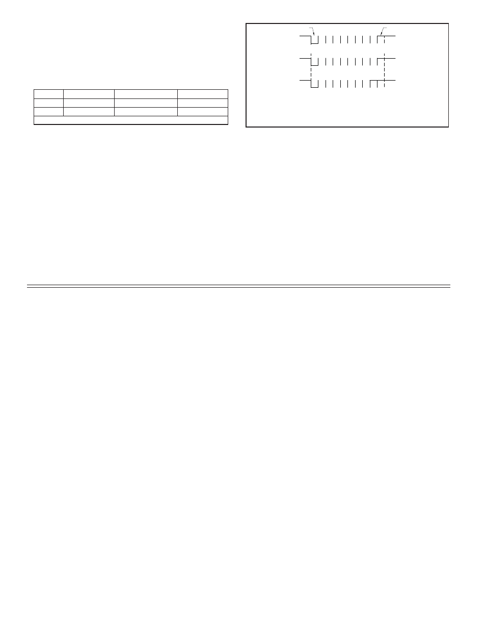
Data is transmitted one byte at a time with a variable idle period between
characters (0 to
). Each ASCII character is “framed” with a beginning start bit,
an optional error detection parity bit and one or more ending stop bits. The data
format and baud rate must match that of other equipment in order for
communication to take place. The figures list the data formats employed by
the meter.
Start bit and Data bits
Data transmission always begins with the start bit. The start bit signals the
receiving device to prepare for reception of data. One bit period later, the least
significant bit of the ASCII encoded character is transmitted, followed by the
remaining data bits. The receiving device then reads each bit position as they
are transmitted. Since the sending and receiving devices operate at the same
transmission speed (baud rate), the data is read without timing errors.
Parity bit
After the data bits, the parity bit is sent. The transmitter sets the parity bit to
a zero or a one, so that the total number of ones contained in the transmission
(including the parity bit) is either even or odd. This bit is used by the receiver
to detect errors that may occur to an odd number of bits in the transmission.
However, a single parity bit cannot detect errors that may occur to an even
number of bits. Given this limitation, the parity bit is often ignored by the
receiving device. The PAX meter ignores the parity bit of incoming data and
sets the parity bit to odd, even or none (mark parity) for outgoing data.
Stop bit
The last character transmitted is the stop bit. The stop bit provides a single
bit period pause to allow the receiver to prepare to re-synchronize to the start of
a new transmission (start bit of next byte). The receiver then continuously looks
for the occurrence of the start bit.
IDLE
0 b
0
1
b
2
b
b
3
b
4
b
5
6
b
1
IDLE
IDLE
IDLE
0
b
b
0
b
1
3
2
b
b
4
b
5
b
6
P 1
IDLE
IDLE
0
b
b
b
0
1
b
b
3
2
4
b
b
5
6
1
1
(7 data, no parity, 2 stop)
(7 data, parity, 1 stop)
(8 data, no parity, 1 stop)
Start bit
Stop bit
Note: b - b is ASCII data.
0
7
7
b
Character Frame Figure
LOGIC
RS232*
RS485*
INTERFACE STATE
1
TXD,RXD; -3 to -15 V
a-b < -200 mV
mark (idle)
0
TXD,RXD; +3 to +15 V
a-b > +200 mV
space (active)
* Voltage levels at the Receiver