Programming module, Installing the unit, Wiring the unit – Red Lion IAMS User Manual
Page 3: Power wiring, Input signal wiring, Analog output wiring, Setpoint output wiring, Supply
3
PROGRAMMING MODULE
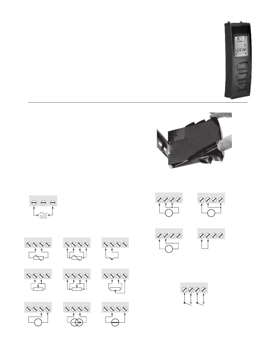
The PGMMOD, Programming/Display Module easily connects to the front of
the IAMS and is used to enter or adjust the programming of the IAMS. Insert
the top of the programming module first, then allow the bottom to lock into the
unit. For applications that require more than one IAMS, the same programming
module can be used to program multiple units. In fact, it can store the
configuration from one IAMS and download the same configuration to another
module. When programming is complete, leave the programming module in
place to display the process data or to remove, press the release tab on the
bottom of the programming module.
Display: LCD display with 4 lines; line 1 is 0.2" (5.5 mm) and displays the
input signal, line 2 is 0.13" (3.33 mm) and displays units, line 3 is 0.13" (3.33
mm) and displays analog output or tag number,
line 4 shows communication and relay status
Programming Mode: Three push buttons
combined with a simple and easily understandable
menu structure and help text guides you
effortlessly through the configuration steps.
Password Protection: Programming access
may be blocked by assigning a password. The
password is saved in the IAMS to guard against
unautherized modifications to the configuration.
A default password of “2008” allows access to all
configuration menus.
INSTALLING THE UNIT
The IAMS is designed to mount to a top hat profile DIN rail. The unit should
be installed in a location that does not exceed the maximum operating
temperature and provides good air circulation. Placing the unit near devices that
generate excessive heat should be avoided.
WIRING THE UNIT
Electrical connections are made via screw-clamp terminals located on the top/
bottom of the unit. All conductors should conform to the unit’s voltage and
current ratings. All cabling should conform to appropriate standards of good
installation, local codes, and regulations. It is recommened that power supplied
to the unit (DC or AC) be protected by a fuse or circuit breaker.
When wiring the unit, compare the numbers on the terminal blocks against
those shown in wiring drawings. Insert the wire under the correct screw-clamp
terminal and tighten until the wire is secure. (Pull wire to verify tightness.)
POWER WIRING
31 32
33
Supply:
Note: For DC power connections,
there are no polarity concerns.
INPUT SIGNAL WIRING
+
-
41 42
44
43
41 42
44
43
41 42
44
43
+
-
41 42
44
43
+
-
Tx
41 42
44
43
41 42
44
43
41 42
44
43
42
44
43
41
41 42
44
43
+
-
RTD, 3- / 4-wire
Resistance,
3- / 4-wire
Voltage
Potentiometer
Current
2-wire transmitter
e
ri
w
-
2
,
e
c
n
a
t
s
i
s
e
R
e
ri
w
-
2
,
D
T
R
TC
4th
wire
4th
wire
self or externally
powered transmitter
current input
needing IAMS power
ANALOG OUTPUT WIRING
11 12
14
13
+
-
mA
11 12
14
13
+
-
V
11 12
14
13
+
-
V
Voltage, 1 V
Voltage, 10 V
Current
11 12
14
13
Not Used
If not using the analog
option, pins 11 and 12
must be shorted.
SETPOINT OUTPUT WIRING
21 22
24
23
R1
R2
Relays