Application, Multiple unit stacking, Ordering information – Red Lion P48 User Manual
Page 5: Water processing application, Accessories
5
APPLICATION
WATER PROCESSING APPLICATION
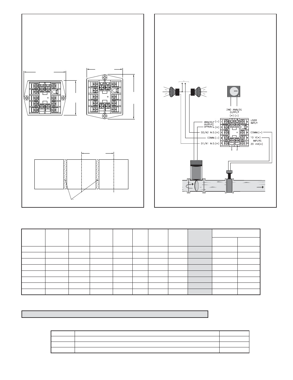
A city water company needs to maintain a steady flow of water for their
customer needs. They have an existing 0 to 10 VDC flow transmitter to
measure the water flow. They need to control the water flow, have a high and
low alarm, and keep a recorded chart of the flow for later reference. The Main
Linear DC output of the P48 can be used to control the position of water
output values per the desired flow setpoint value. The P48 relay outputs can
be programmed to give a high flow alarm and a low flow alarm. With the
Second Linear DC output model, the flow measurement to the P48 can be
converted from 0-10 V to 4-20 mA and retransmitted to a 4-20 mA chart
recorder.
CHART
RECORDER
HIGH
ALARM
LOW
ALARM
WATER FLOW
ALARM
POWER
+
-
CONTROL
VALVE
FLOW
SENSOR
UNIT POWER
MULTIPLE UNIT STACKING
The P48 is designed for close spacing of multiple units. Units can be
stacked either horizontally or vertically. For vertical stacking, install the panel
latch with the screws to the sides of the unit. For horizontal stacking, the panel
latch screws should be at the top and bottom of the unit. The minimum
spacing from center line to center line of units is 1.96" (49.8 mm). This
spacing is the same for vertical or horizontal stacking.
Note: When stacking units, provide adequate panel ventilation to ensure that
the maximum operating temperature range is not exceeded.
1
2
3
4
5
6
7
8
9
10
13
14
12
11
2.39 (60.7)
MAX.
1.96 (49.8)
MAX.
PANEL LATCH INSTALLED FOR
VERTICAL UNIT STACKING
HORIZONTAL UNIT STACKING
PANEL LATCH INSTALLED FOR
MAX.
2.39 (60.7)
MAX.
1.96 (49.8)
1
2
3
4
5
6
7
8
9
10
13
14
12
11
1.96 (49.8)
MIN.
IF NEMA 4 IS NOT REQUIRED,
THIS PANEL MATERIAL MAY BE REMOVED.
PANEL
CUT-OUT
STANDARD
PANEL CUT-OUT SPACING FOR MULTIPLE UNIT STACKING.
HORIZONTAL ARRANGEMENT SHOWN.
(Terminal assignments are model number dependent.)
ORDERING INFORMATION
Options and Output Boards are factory configured per the part number specified. Part numbers without replacement output boards listed must be returned
to the factory for output board replacement.
DEDICATED
MAIN CONTROL
O1 OUTPUT
MAIN CONTROL
O1 or
A1(ALARM 1)*
DEDICATED
ALARM 1
A1 OUTPUT
A2 (ALARM 2)
OR O2
(SECONDARY)*
REMOTE
SETPOINT
INPUT @
RS485 @
MAIN
ANALOG
OUTPUT** @
SECOND
ANALOG
OUTPUT** @
PART NUMBERS
85 to 250 VAC
18-36 VDC/24 VAC
REPLACEMENT
OUTPUT
BOARD
YES
P4800001
P4800011
NA
Relay
P4810000
P4810010
RBD48100
Relay
Relay
YES
P4810101
P4810111
NA
Relay
Relay
YES
YES
P4810105
P4810115
NA
Relay
Relay
YES
YES
P4810107
P4810117
NA
Relay
Relay
YES
YES
P481010A
P481011A
NA
Relay
Relay
Relay
P4811100
P4811110
RBD48111
Relay
Relay
Relay
YES
P4811102
P4811112
RBD48111
* This output is programmable as either Control (PID) or as an Alarm.
** These part numbers are jumper and program selectable for either a current or a voltage Linear DC output.
@ These part numbers are equipped with a second setpoint.
MODEL NO.
DESCRIPTION
PART NUMBERS
ICM5
ICM4
SFCRM
Three Way Isolated RS232/RS485 Serial Converter Module
RS232/RS485 Serial Converter Module
ICM50000
ICM40030
SFCRM
ACCESSORIES
Option Boards are installed at the factory for the appropriate models. These boards are only needed for field replacement.
Crimson 2 PC Configuration Softwware for Windows 98, ME, 2000 and XP (for RS485 models)
*Crimson Software is available for download from http://www.redlion.net