Wiring connections, Configuration, Installation – Red Lion AFCM User Manual
Page 2: Dip switch s1, Dip switch s2, Output signals, Fault detection, T rail installation
2
11. CERTIFICATIONS AND COMPLIANCES:
1
Criterion B: Temporary impairment to operational behavior that is corrected
by the device itself.
2
Criterion A: Normal operating behavior within the defined limits.
3
Class A: Area of application industry.
12. CONNECTIONS: Wire Gauge: 24-12 AWG, Stripping length: 0.47" (12 mm)
13. CONSTRUCTION: Polybutylenterephthalate PBT, black
14. MOUNTING: Standard DIN top hat (T) profile rail according to EN50022
- 35x7.5
15. WEIGHT: 2 oz. (54 g)
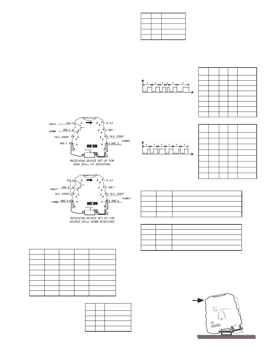
WIRING CONNECTIONS
Primary power is
connected to terminals
7 or 3 (19.2 – 30
VDC) and 8 or 4
(GND 3). For best
results, the Power
should be relatively
“clean” and within the
specified variation
limits. Drawing power
from heavily loaded
circuits or from
circuits that also
power loads that cycle
on and off, should be
avoided.
The input signal is
connected to terminal
1 (In UI) and 2 (GND
1). Connections for
the output signal is on
terminals 5 (Out f) and
6 (GND 2).
CONFIGURATION
DIP Switch S1
Using DIP switch S1, you can set the input values, and the values for Moving
Average Filter and Over sampling.
The moving average filter can group
values (1, 2, 4, 6) using moving window
averaging to form a new measured value. In
moving window averaging, the average of a
fixed number of measured values is taken,
whereby the oldest value is always dropped
and the most recent added.
In order to smooth the measured values, an
average can be formed from several measured
values (1, 10, 50, 100). This process is called
Over sampling. In oversampling, the average
is updated every time the selected number of
values is reached.
DIP Switch S2
Using DIP switch S2, you can set the output values, the output type and fault
detection.
Output Signals
Frequency Output:
Variable frequency/period duration T
PWM Output
(Pulse Wide Modulation):
Variable pulse to pause ratio/fixed
period duration T
Change can only be read by PWM
input meters.
Fault Detection
INSTALLATION
The unit is equipped with a universal mounting foot for attachment to
standard DIN style top hat (T) profile rail according to EN50022 - 35 x 7.5 and
35 x 15. The unit should be installed in a location that does not exceed the
maximum operating temperature and provides good air circulation. Placing the
unit near devices that generate excessive heat should be avoided.
T Rail Installation
To install the AFCM on a “T”
style rail, angle the module so
that the top groove of the “foot”
is located over the lip of the top
rail. Push the module toward the
rail until it snaps into place. To
remove a module from the rail,
insert a screwdriver into the slot
on the bottom of the “foot”, and
pry upwards on the module until
it releases from the rail.
1
2
3
4
ANALOG IN
0 – 10V
ON
1 – 5V
ON
0 – 5V
ON
2 – 10V
ON
ON
0 – 20 mA
ON
ON
ON
4 – 20 mA
ON
ON
ON
0 – 10 mA
ON
ON
ON
ON
2 – 10 mA
5
6
MOVING WINDOW
AVERAGING
1 value
ON
2 values
ON
4 values
ON
ON
6 values
1
2
3
4
FREQUENCY
OUTPUT
0 - 10 kHz
ON
0 - 5 kHz
ON
0 – 2.5 kHz
ON
ON
0 - 1 kHz
ON
0 - 500 Hz
ON
ON
0 - 250 Hz
ON
ON
0 - 100 Hz
ON
ON
ON
0 - 50 Hz
5
6
INPUT OVER RANGE
Freeze at 100% measuring range end value
ON
105% measuring range end value
ON
110% measuring range end value
ON
ON
7
8
INPUT UNDER RANGE
Freeze at 100% measuring range start value
ON
105% measuring range end value
ON
110% measuring range end value
ON
ON
Fault detection OFF (stops at start value)
Conformance With EMC Guideline 89/336/EEC And Low Voltage Directive 73/23/EEC
Immunity to Interference According to EN 61000-6-2
Discharge of static electricity (ESD)
EN 61000-4-2
Criterion B
1
Electromagnetic HF field
EN 61000-4-3
Criterion A
2
Fast transients (Burst)
EN 61000-4-4
Criterion B
1
Surge voltage capacities (Surge)
EN 61000-4-5
Criterion B
1
Conducted disturbance
EN 61000-4-6
Criterion A
2
Noise Emission According to EN 61000-6-4
Noise emission of housing
EN 55011
Class A
3
ON
7
8
1 value
ON
10 values
ON
50 values
ON
ON
100 values
OVER SAMPLING
1
2
3
4
ON
7.8 Hz
ON
ON
3.9 Hz
ON
ON
1.9 Hz
ON
ON
ON
977 Hz
ON
ON
488 Hz
ON
ON
ON
244 Hz
ON
ON
ON
122 Hz
ON
ON
ON
ON
61 Hz
PWM
OUTPUT
Fault detection OFF (continues past end value)