State Tilt Roof User Manual
Page 3
3
Figure 6.
3. Determine the location of the flashing and cut a slit in the
roofing paper so the upslope edge of the flashing can
slide under the paper when installed. See Figures 5 & 6.
4. Once the flashing location has been determined, mark
the position of the center of the flashing bushing on the
roof paper. Remove the flashing.
5. Drill a 5/16” hole between the rafters at the center mark
of the flashing bushing.
Figure 7.
6. Slide the flashing back under the roof paper and position
it so that the center of the flashing bushing is aligned
with the center of the drilled hole.
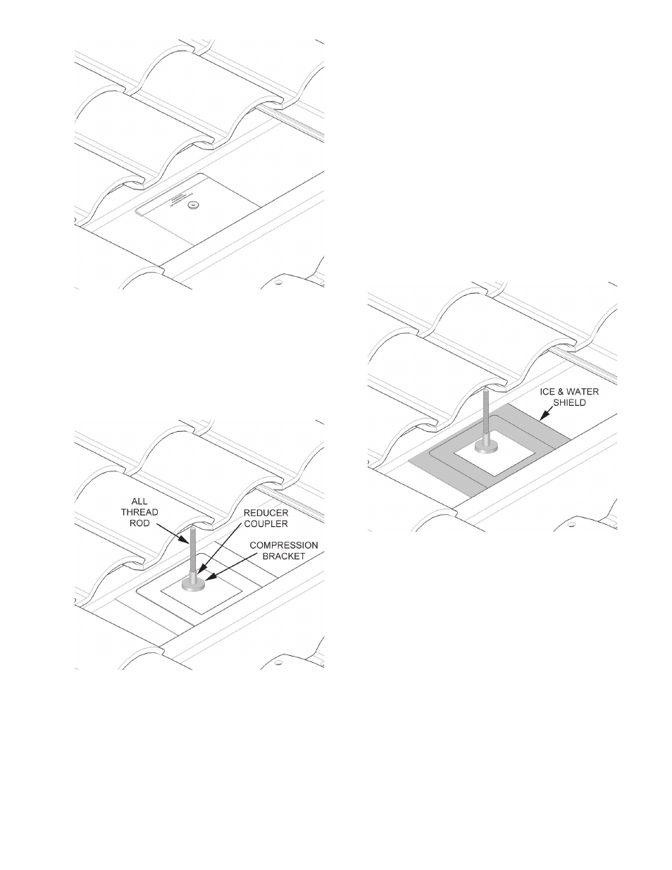
7. A piece of 12” length of stainless steel 5/16” all-thread
is then inserted through the hole in the roof and the
flashing bushing. Attach the compression bracket
washer and 5/16” x 3/8” SS reducer coupler to the 5/16”
SS –all thread as shown. The all-thread should extend
about 4” below the roof rafters. See Figures 7 & 16.
8. Fabricate spanners, one for each mounting bracket,
using a 2” x 4” or similar lumber. Spanners must be
long enough to span at least two rafters. In the attic or
crawl space drill a 5/16” hole through each spanner and
insert the all-thread through it. Secure each spanner to
the rafters with decking or wood screws. See Figure 16.
9. Fabricate spacer blocks, one for each mounting bracket,
using a 2” x 4” or similar lumber the same width of the
rafter next to each all-thread. Place spacer blocks next
to the all-thread between the spanner and roof. Secure
each spacer block to the spanners with decking or
wood screws. Spacer blocks are necessary to avoid
deformation of the roof. See Figure 16.
10. With a stainless steel nut, lock washer and fender
washer secure the all-thread to each spanner. Tighten
down until the compression bracket washer is tightly
secured to the roof and flashing (approx. 97 inch
pounds). Be careful not to over tighten and dish out
the roof underneath the mounting bracket washer and
flashing. See Figure 16.
Figure 8.
11. Install an Ice & Water Shield (not included) around the
flashing to provide a water tight seal. See Figure 8.