Physical description, Operator manual – tra series amplifiers page - 5, Amplifier front panel – Ashly TRA-4150 User Manual
Page 5: Amplifier rear panel
Operator Manual – TRA Series Amplifiers
Page - 5
All Rights Reserved
Rev 1.2 0306
Physical Description
TRA-Series models generally have the same physical design, though there are obvious
differences between two and four channel versions. The model number is indicated on the
left side of the front panel
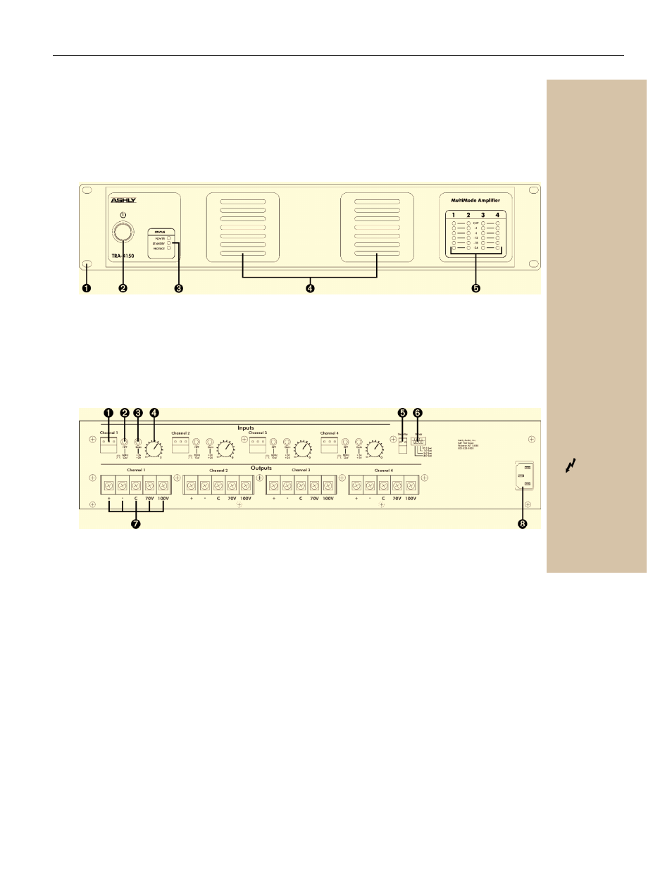
Amplifier Front Panel
1. Mounting Holes – For rack mounting.
2. Power Switch – Switches the unit on or off
3. Status LEDs – Indicate status of: Power,
Standby, and Protect
4. Air Vents
5. Channel LEDs – The Sig LED will begin to
light when the output voltage reaches
approximately 0.3 volts. When clipping occurs
the Clip LED will light.
Amplifier Rear Panel
1. 3-Pin Euroblock Input Connectors – These
connectors are used for all input signals.
2. HPF Switch – sets the High Pass Filter for
each channel to 80Hz or Off.
3. Gain Switch – sets the amplifier gain to +36dB
or +26dB sensitivity.
4. Channel Attenuators – These knobs adjust
the attenuation of the input signal of each
channel from to 0.
Items 1-4 are identical on all channels of all TRA-Series
amplifiers, 2 or 4 channel.
5. Standby Connector – This 2-Pin Euroblock
connector provides for remote standby
switching. The Power switch must be in the On
position for the Standby connector to be active.
6. Delay Switches – These switches provide turn
on delay when the Standby connector is used.
The switches are additive, providing as much
as 7.5 seconds of delay
7. Screw Terminal Output Connectors – These
connectors provide the amplifiers output signal
for each channel. The positive (+) and negative
(-) connectors should be used for low-
impedance applications. For constant voltage
applications, connect the negative wire (-) of
your system to the C (common) terminal and
the positive (+) wire to the appropriate Constant
Voltage output for your setup (70V or 100V).
8. Mains Connector - Connection to the mains is
via this 3-Prong IEC connector
WARNING: Do not remove the mains connector ground. It is illegal and dangerous.
Important Safety
Instructions – 2
Introduction - 3
The TRA Series - 4
Physical Description - 5
Front Panel
Rear Panel
Installation - 6
Operation - 8
Troubleshooting - 9
Spec Table - 10
Dimensions - 11
Warranty - 12
Terminals marked
with are HAZARDOUS
LIVE. External wiring to
these terminals/
connectors requires
installation by trained
personnel, or pre-
manufactured cables