Flaming River Power Rack & Pinion Mustang 1979-93 User Manual
Page 2
79-93 PWR Rack
4/24/2009
1
Original Rack Removal
Note: For vehicles with airbags disconnect the negative battery cable and the positive. Wait 2 minutes before
proceeding. This is to avoid any accidental deployment of the airbags.
Note: We recommend the use of new outer tie rod ends and mounting bushings when installing this product to
obtain the proper performance.
Note: A front end alignment is necessary after installation.
1) Position the front wheels straight ahead and the lock the steering column in place.
2) Raise your vehicle and ensure that it is properly supported.
3) Disconnect your power steering lines from the rack and pinion and cap the ends to make sure that no
contamination gets into the lines.
4) Remove the pinch bolt that retains the rag joint to the rack and pinion.
5) Remove the cotter pins and castle nuts from the outer tie rod ends and then remove the outer tie rod ends
from the spindles.(A tie rod end puller or pickle fork may be necessary.)
6) Next remove the nuts and bolts that mount the rack to the cross member.
7) As you lower the steering gear separate the steering shaft from the input shaft of the steering gear.
8) Remove the bolt that retains the steering shaft to the column and remove the steering shaft from the car.
New Flaming River Rack Installation
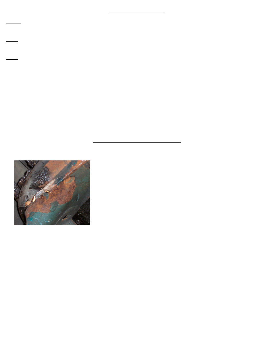
1) Before installing the new rack you must first notch the driver’s side engine mounting boss 3/8” wide x ¾”
long. (See photo below)
2) Install the lower u-joint from the shaft kit onto the pinion shaft of the new power rack.
3) Install the rear portion of the rack and pinion mounting bushings into the mounting bosses of the new
rack.
4) Slide rack over the mounting pins and install the front portion of the mounting bushings.
5) Install the steering gear mounting bolts, nuts and washers and tighten to 30-40 ft lbs.
6) Insert splined shaft in to the opposite end of the u-joint connecting to the rack. (Note: This shaft may
need to be trimmed to the correct length for your application.)
7) Slide top u-joint over shaft.
8) Insert tongue into end of steering column shaft and then into DD side of top u-joint, next install through
bolt. (Do not tighten bolt at this time).
9) Adjust each u-joint so that there is 7/8” of shafting into each yoke; make sure the set screw on the
pinion shaft is set in the groove.
10)Snug each set screw so that it will leave a mark on the shaft including the tongue.
11)Remove the shaft and dimple (see fig B) each set screw mark using a ¼” drill bit Note: do not dimple
pinion shaft on rack and pinion damage to rack may occur.