Tuff Country 55900 - Toyota Tundra 99-04 4.5 kit User Manual
Page 3
Hardware bag 55900NB1 includes:
Description
Quantity
M12FN (M12 fine nut)
1
M12LWA ( 12 mm lock washer)
1
51634B (5/16” x 3/4” bolt)
2
5161B (5/16” x 1” bolt)
5
516114B (5/16” x 1 1/4” bolt)
1
14WA (1/4” USS flat washer)
16
516UN (5/16” unitorque nut)
8
381B (3/8” x 1” bolt)
4
38112 (3/8” x 1 1/2” bolt)
2
516WA (5/16” USS flat washer )
14
38UN (3/8” unitorque nut)
10
716112B (7/16” x 1 1/2” bolt)
4
716LWA (7/16” lock washer)
4
12114B (1/2” x 1 1/4” bolt)
2
12112B (1/2” x 1 1/2” bolt)
2
716WA (7/16” USS flat washer )
8
12UN (1/2” unitorque nut)
4
916214B (9/16” x 2 1/4” bolt)
1
916212B (9/16” x 2 1/2” bolt)
1
12WA (1/2” USS flat washer)
7
916LWA (9/16” lock washer)
1
34412B (3/4” x 4 1/2” bolt)
2
34512B (3/4” x 5 1/2” bolt)
2
34WA (3/4” USS flat washer)
8
34UN (3/4” unitorque nut)
4
Hardware bag 55900NB2 includes:
Description
Quantity
PB2408 (poly bushing)
4
S10082 (.875” x .563” x 2.080” sleeve)
2
MO2382 (poly bushing)
2
S10076 (.750” x .629” x 2.875 sleeve)
1
MO3354 (poly bushing)
2
S10075 (.750” x .625” x 1.275 sleeve)
1
S10140 (fender washer)
2
BLR09 (brakeline bracket)
2
BLR01 (brakeline bracket)
2
T5I-12L (knuckle washer)
2
5U-5161316R (5/16” x 1 3/16” x 2” round u-bolt)
4
516FN (5/16” flange nut)
8
ZIPTIE (zip tie)
2
SB34 (shock bushing)
2
Hardware bag 916NW includes:
Description
Quantity
SUW-916 (9/16” u-bolt washer)
8
916HN (9/16” harden washer)
8
Please follow instructions carefully:
Before installation begins, measure from the center of
the hub, to the bottom of the fender well, and record
measurements below.
Pre-installation measurements:
Driver side front:_________________________________
Passenger side front:_____________________________
Driver side rear:__________________________________
Passenger side rear:______________________________
At the end of the installation take the same
measurements and compare to the pre-installation
measurements.
Post-installation measurements:
Driver side front:_________________________________
Passenger side front:_____________________________
Driver side rear:_________________________________
Passenger side rear:______________________________
Front end installation:
1. To begin installation, block the rear tires of the vehicle so
that the vehicle is stable and can’t roll backwards. Safely lift
the front of the vehicle and support the frame with a pair of
jack stands. Place a jack stand on both the driver and pas-
senger side. Next, remove the front wheels and tires from
both sides.
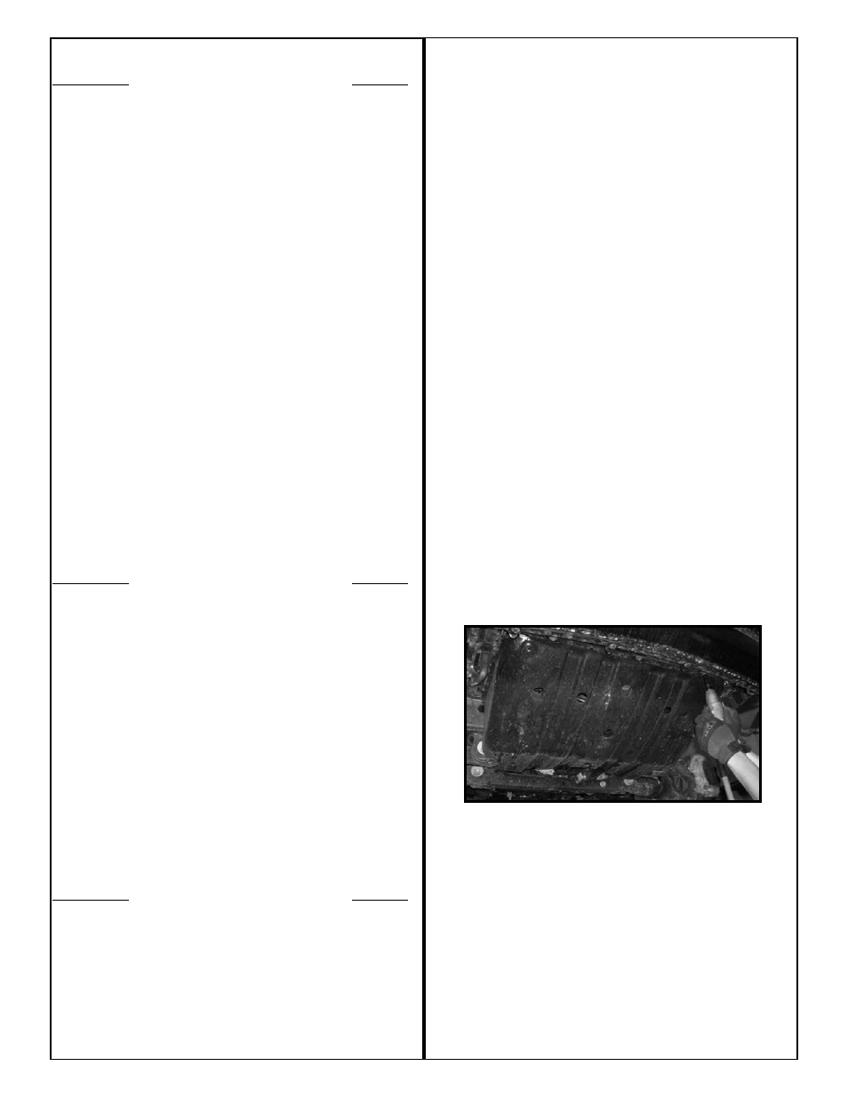
2. Remove the front skid plate. Save the skid plate and hard-
ware.
3. Working on the driver side, remove the brake line bracket
that connects to the side of the frame rail. Save the hard-
ware. Repeat procedure on the passenger side.
4. Working on the driver side, remove the hardware from the
sway bar end link and save the hardware for later re-instal-
lation. Repeat procedure on passenger side.