Tuff Country 55900 - Toyota Tundra 99-04 4.5 kit User Manual
Page 11
55900NB1. Working on the driver side, secure the previous-
ly installed ball joint spacer and the knuckle support bracket
to the neck of the knuckle using the new 7/16” hardware. Get
the 7/16” hardware started but DO NOT tighten at this point.
Secure the driver side knuckle support bracket to the body of
the knuckle using the new 5/16” x 1 3/16” x 2” round u-bolts
and hardware but DO NOT tighten at this point. Secure the
3/8” x 1 1/2” bolt to the new knuckle support bracket but do
not tighten at this point. Move back to the new 7/16” x 1 1/2”
bolt and hardware and add some loctite and torque to 45 ft
lbs. Then tighten the 3/8” x 1 1/2” bolt until it makes contact
with the body of the knuckle. Once the new 3/8” x 1 1/2” bolt
makes contact with the knuckle, torque the U-bolts to 24 ft
lbs. Repeat procedure on passenger side.
65. Locate the driver side and passenger side sway bar drop
brackets. Also, locate (4) 3/8” x 1” bolt, (8) 5/16” USS flat
washers and (4) 3/8” unitorque nuts from hardware bag
55900NB1. Working on the driver side, secure the new driv-
er side sway bar drop bracket to the stock location and
secure using the new 3/8” x 1” bolt and hardware. Make sure
to use loctite and torque to 32 ft. lbs. Special note: once
the new sway bar drop bracket is installed, it will move
the sway bar down and towards the rear of the vehicle.
Repeat procedure the passenger side.
66. Locate the sway bar and the OE sway bar hardware.
Working on the driver side, install the sway bar to the newly
installed sway bar drop brackets and secure using the stock
hardware. Make sure to use loctite and torque to 18 ft lbs.
Repeat procedure on the passenger side.
67. Locate the sway bar end link hardware. Working on the
driver side, install the sway bar to the sway bar end link posi-
tion and secure using the stock hardware. Make sure to use
loctite and torque to 18 ft lbs. Repeat procedure on the pas-
senger side.
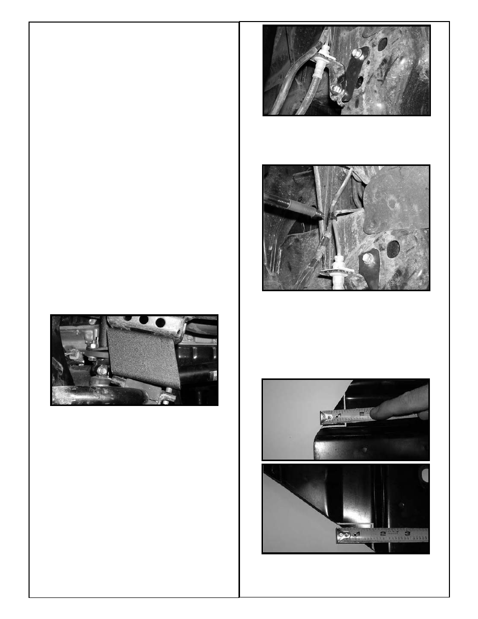
68. Locate (2) BLR01 front brake line relocation brackets
from hardware bag 55900NB2. Locate (2) 5/16” x 3/4” bolts,
(4) 1/4” USS flat washers and (2) 5/16” unitorque nuts from
hardware bag 55900NB1. Also, locate the stock brake line
bracket hardware. Working on the driver side, attach the new
brake line relocation bracket to the frame location and
secure using the stock hardware. Do not tighten at this
point. Now attach the stock brake line bracket to the newly
installed brake line relocation bracket using the new 5/16” x
3/4” bolt and hardware. Make sure to use loctite and torque
to 14 ft lbs. Add some loctite to the stock bolt holding the
new brake line relocation bracket to the frame location and
torque to 12 ft lbs. Repeat procedure on the passenger side.
69. Locate the (2) zip ties from hardware bag 55900NB2.
Working on the driver side, zip tie the stock brake line and
the stock ABS lines together. Cut off the excess part of the
zip tie. Repeat procedure on the passenger side.
70. Locate the stock skid plate. Place the skid plate flat on a
work bench. Working on the driver side of the skid plate,
measure from the leading edge of the skid plate towards the
back of the skid plate 1 1/4” and scribe a mark with white out
or a white marker. Now measure 1 1/2” from the leading
edge towards the inside of the vehicle and scribe a mark.
Repeat procedure on the passenger side of the skid plate.
With a suitable cutting tool, carefully notch out the skid plate
on the lines that were scribed earlier in this step.
71. Locate the stock skid plate hardware. Install the modified
skid plate into the OE location and secure using the hard-
ware. Make sure to use loctite and torque to 18 ft lbs.