Merit Medical Mentor Simulator/Tester User Manual
Page 5
3
6. Generate a positive pressure on the monitor
screen by rotating the Pressure Regulator Knob
on the Mentor toward the (+) sign. For
example, apply a pressure of 100 mmHg to
the transducer so the Mentor LCD reads 100
mmHg. Now check that the signal displayed on
the monitor screen reads 100 mmHg. If it is
slightly above or below 100 mmHg, adjust the
gain control of the monitor to move the signal
tracing to the 100 mmHg position.
7. After any adjustments of the gain control,
re-check the zero reference line. Compare the
readings displayed on the Mentor and the
monitor screen. If the measurements are the
same, the system is calibrated correctly. If not,
zero the monitor and repeat steps 6 and 7.
PRECAUTION: If, after following these
calibration verification procedures, the pressure
readings on the monitor screen and the Mentor
LCD are not the same and greater than the sum
of the accuracy specifications of both the
transducer and the monitor, start the trouble-
shooting procedures outlined in Section IV.
8. Disconnect the Mentor from the physiological
pressure monitoring set-up prior to measuring
patient pressures. Also check that the fluid lines
are thoroughly flushed and debubbled prior to
measuring the patient’s physiological pressures.
••••••••••SECTION II ••••••••••
VERIFYING THE CALIBRATION OF
THE PHYSIOLOGICAL PRESSURE
MONITORING SYSTEM WHEN USING
TRANSDUCERS WITH BACKSIDE
CALIBRATION PORTS OR
CALIBRATION PORTS LOCATED IN
THE DISPOSABLE CABLE
1. Prior to connecting the Mentor to a
transducer, turn the On/Off button to the On
position to automatically zero the Mentor to
atmospheric pressure.
2. Open the transducer to air. Zero the monitor
by using the “balance” or “zero” button on the
monitoring system’s control panel.
PRECAUTION: If the transducer signal does
not appear on the zero reference line after
using the monitor’s zero button, adjust the
position of the signal trace so that it is exactly on
top of the zero reference line by adjusting the
offset or signal position control knob of the
amplifier (as outlined in the monitoring
equipment’s Operator Manual).
3. For calibration, set a standard reference
display on the monitor screen. For example, a
common reference display is a 0 to 300 mmHg
scale with full deflection equalling 300 mmHg.
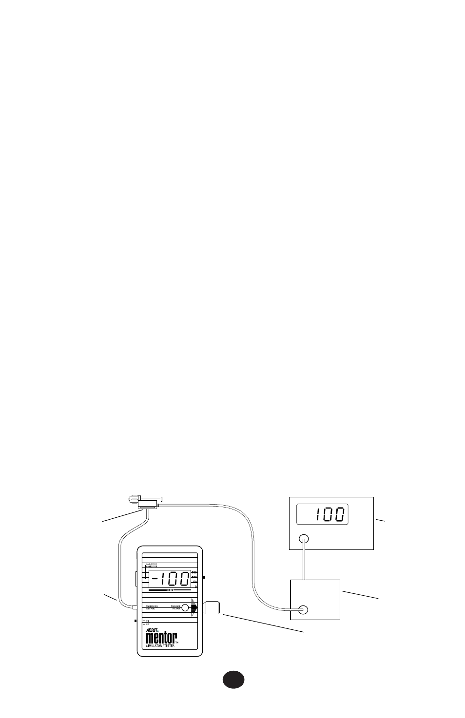
Diagram B: Backside Verification of Calibration
TRANSDUCER BACKSIDE
CALIBRATION PORT
PRESSURE MONITORING
TUBING (Cat # PM6012P)
PRESSURE REGULATOR KNOB
MONITOR
MONITOR
PRE-AMP