Asus P4GE-V User Manual
Page 51
ASUS P4GE-V motherboard user guide
2-25
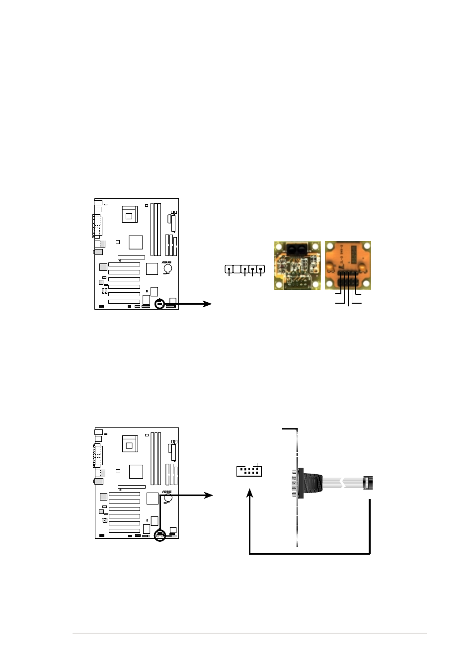
12. Infrared module connector (5-1 pin IR1)
This connector supports an optional wireless transmitting and receiving
infrared module. This module mounts to a small opening on system
chassis that support this feature. You must also configure the UART2
Use As parameter in BIOS to set UART2 for use with IR. See section
“4.4.2 I/O Device Configuration” for details.
Use the five pins as shown in Back View and connect a ribbon cable
from the module to the motherboard SIR connector according to the
pin definitions.
13. Serial port 2 connector (10-1 pin COM2)
This connector accommodates a second serial port using an optional
serial port bracket. Connect the bracket cable to this connector then
install the bracket into a slot opening at the back of the system chassis.
P4GE-V
®
P4GE-V Serial COM2 Bracket
PIN 1
COM2
P4GE-V
®
P4GE-V Infrared Module Connector
Back View
+5V
IRTX
IRRX
(NC)
GND
Front View
IR_CON1
+5V
IRRX
IR
TX
GND
1
- PCI Express Audio Card Xonar DX (70 pages)
- Xonar DX (80 pages)
- Xonar DX (10 pages)
- Xonar D2X (88 pages)
- Xonar D2X (84 pages)
- D2X (88 pages)
- Audio Card Xonar D2X (70 pages)
- ROG Xonar Phoebus (72 pages)
- ROG Xonar Phoebus (122 pages)
- Xonar DSX (26 pages)
- Xonar DSX (29 pages)
- Xonar DGX (33 pages)
- Xonar DGX (58 pages)
- Xonar DGX (38 pages)
- Xonar DG (58 pages)
- Xonar DG (32 pages)
- Xonar DG (28 pages)
- Xonar DG (54 pages)
- Xonar Essence ST (52 pages)
- Xonar Essence ST (35 pages)
- Xonar Essence ST (40 pages)
- Xonar Essence ST (53 pages)
- Xonar DS (54 pages)
- Xonar DS (33 pages)
- Xonar Xense (45 pages)
- Xonar Xense (47 pages)
- Xonar Xense (70 pages)
- Xonar U3 (38 pages)
- Xonar U3 (56 pages)
- Xonar Essence STX (49 pages)
- Xonar Essence STX (10 pages)
- Xonar Essence STX (32 pages)
- Xonar D1 (80 pages)
- Xonar D1 (10 pages)
- XONAR D1 E4009 (72 pages)
- Xonar D1 (72 pages)
- Xonar Essence One (7 pages)
- Xonar Essence One (5 pages)
- Xonar HDAV 1.3 (100 pages)
- Motherboard M4A78-EM (64 pages)
- A7N8X-VM/400 (64 pages)
- K8V-XE (86 pages)
- K8V-XE (20 pages)
- M2R32-MVP (60 pages)
- M2R32-MVP (160 pages)