Manley The WAVE DAC/Preamp 20 Bit Version Serial Code WAVE000-015 1999 - 2002 User Manual
Page 9
DAC / Preamp
by MANLEY
The WAVE
ANALOG 4
ANALOG 3
ANALOG 2
ANALOG 1
AES / EBU
LOGIC DESIGNED BY J. GARSZVA
PCB'S & CHASSIS BY B. HERNANDEZ
LINE STAGE DESIGNED BY C. HUTCHISON
AN EVEANNA MANLEY PRODUCTION
email: [email protected]
PHONE (909) 627-4256 FAX (909) 628-2482
13880 MAGNOLIA AVE., CHINO, CA 91710
MANLEY LABORATORIES
PIN 3 = LOW = NEGATIVE PHASE
PIN 2 = HOT = POSITIVE PHASE
PIN 1 = SHIELD = GROUND
XLR INPUTS AND OUTPUTS
MOISTURE
THIS EQUIPMENT TO RAIN OR
ELECTRIC SHOCK DO NOT EXPOSE
TO REDUCE THE RISK OF
SERIAL NUMBER
PERSONNEL ONLY
REFER SERVICING TO QUALIFIED
SHOCK. DO NOT OPEN.
CAUTION - RISK OF ELECTRIC
DIGITAL I/0
POWER SUPPLY
GROUND
CHASSIS
CIRCUIT
OUTPUT
DIGITAL
SELECTED
ST
TOSLINK
S/PDIF
LEFT
RIGHT
SEND
INSERT
RETURN
INSERT
BALANCED
UNSWITCHED
OUTPUT 2
OUTPUT 3
OUTPUT 1
P O N M L K J I H G F E D C B A
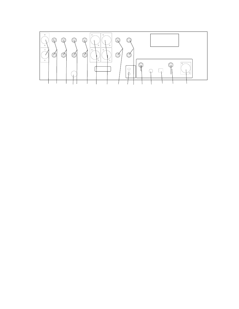
note) This panel is the standard layout for the WAVE, however, Manley Labs does custom configure
individual units to order with alternative connectors and different variations of balanced and unbalanced inputs
and outputs. While the drawing may not accurately depict your jacks, the locations should be valid.
A) AES/EBU DIGITAL INPUT. Connect the appropriate balanced digital input here. The digital interconnect
should be a proper digital cable optimised for 110 ohm termination.
B) S/PDIF INPUT. As above, but the consumer version, unbalanced 75 ohm. Very popular but this interface is
designed for shorter cables. Both the AES/EBU and S/PDIF are transformer coupled.
C) TOSLINK INPUT. Another popular standard interconnect and uses plastic optical fiber. Unfortunately it is
best avoided unless no other option exists.
D) ST INPUT. Generally the best choice as it uses a premium glass fiber that provides the widest bandwidth,
fast square waves and electrical isolation. Unfortunately, many players do not include this because the cost of
interfaces and cable is higher. This standard was created by AT&T and adopted for digital audio. The
ULTRAANALOG AES-21 digital reciever module offers exceptional jitter rejection but we can often hear an
improvement comparing ST to AES or S/PDIF cables. These bayonette style connectors require a quarter
turn clockwise to lock. They can be fragile so some degree of gentleness is best when connecting /
disconnecting or moving the converter.
E) SELECTED DIGITAL OUTPUT. S/PDIF output follows the last selected digital input even if one of the
Analog Inputs has been selected for listening. This allows recording and digital dubs. The front panel LEDs
indicate the last digital source. Panasonic DATS may or may not be capable of dealing with this output.
F) ANALOG 1. The standard Wave provides 2 stereo unbalanced RCA inputs (compatable with most hi-fi and
consumer equipment) and 2 balanced XLR stereo inputs (compatable with some premium audiophile
equipment and pro gear). These are not phono inputs (which require way more gain, different impedances,
and RIAA deemphasis) but the output from a phono preamp, FM receiver, tape deck or VCR, etc should be
connected here (or ANALOG 2, 3 or 4) and this input is selected with the A 1 button.
G) GROUND TERMINALS. These 'ground posts' are intended to help in some installations particularly where
a special audio grounding scheme is used. The top post is the audio circuit ground and the bottom is chassis
and AC third pin ground. For almost all applications these posts are connected together with a strap or solid
piece of wire. If you are getting hums and buzzes, this is a good place to sart experimenting, and why we
include them.
H) ANALOG 2. Just like ANALOG 1 and corresponds to the A 2 button
I) ANALOG 3. Just like ANALOG 1 except typically a balanced XLR connector.
J) ANALOG 4. Just like ANALOG 3.
9