Block diagram – Manley The WAVE DAC/Preamp 20 Bit Version Serial Code WAVE000-015 1999 - 2002 User Manual
Page 18
REGULATORS
RLY
+5
R
-15
L
-15
DAC 5V
R
+15
L
+15
DAC 15V
ANALOG BOARD
FRONT PANEL BOARD
ANALOG BOARD
REMOTE
RELAY DRIVE
LEDS
LOGIC
TRANSMIT
IR
RECEIVER
IR
ADDRESS DIP
ADDRESS DIP
ADDRESS DIP
PANEL BUTTONS
LEDS & RELAYS
WARM-UP
TUBE 12V
TUBE 300V
STANDBY
LOGIC
POWER SUPPLY
INSERT
MUTE
INSERT
LINE AMP
VACUUM TUBE
LINE AMP
VACUUM TUBE
OUT 1
OUT 2
OUT 3
OUT 3
OUT 2
OUT 1
A4
A1
A2
A3
A4
A3
A2
A1
FILTER
ALIAS
ANTI-
PASSIVE
FILTER
ALIAS
ANTI-
PASSIVE
DIGITAL BOARD
RATE LEDS
SAMPLE
DAC
ULTRAANALOG
DAC
ULTRAANALOG
PHASE
HDCD
REMOVAL
JITTER
AES21
OUTPUT
DIGITAL
ST
TOSLINK
S/PDIF
AES/EBU
BLOCK DIAGRAM
18
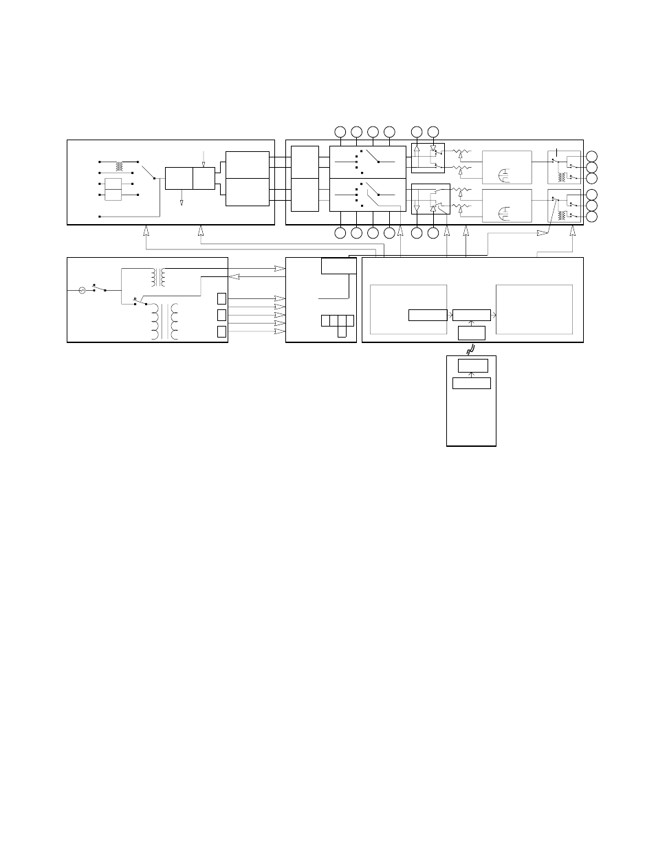
This is a roughblock diagram of the Wave with a little liberty taken for the sake of clarity.
The input selector consists of a number of discrete relays and is not a rotary switch but acts
like one except with less L/R crosstalk. Also this is fully balanced so both halves of the
signal are switched.
The Insert block shows amplifiers needed for balanced to unbalanced conversion when the
insert is unbalanced and uses RCA connectors. The balanced option eliminates those
amps because they are not needed for short cable runs.
The circles represent input and output jacks and don't really show balanced and
unbalanced lines. The Mute Switch is not in-line and just shorts the output to ground for
muting. Output 2&3 when off also short to ground for silence.
The 4 deck motorized volume pot is shown on the Analog Board but it lives on its own
board along with the motor driver.
Except for the main cable between the Power Supply and the Analog Board, no attempt
was made to show power supply lines, however the location of some of the important
regulators is shown. There are 6 more 5V regs on the DAC board which are fed pre-
regulated 8V from the power supply.
FUSE PWR
STANDBY