12ax7, Digital to analog converter – Manley The WAVE DAC/Preamp 20 Bit Version Serial Code WAVE000-015 1999 - 2002 User Manual
Page 12
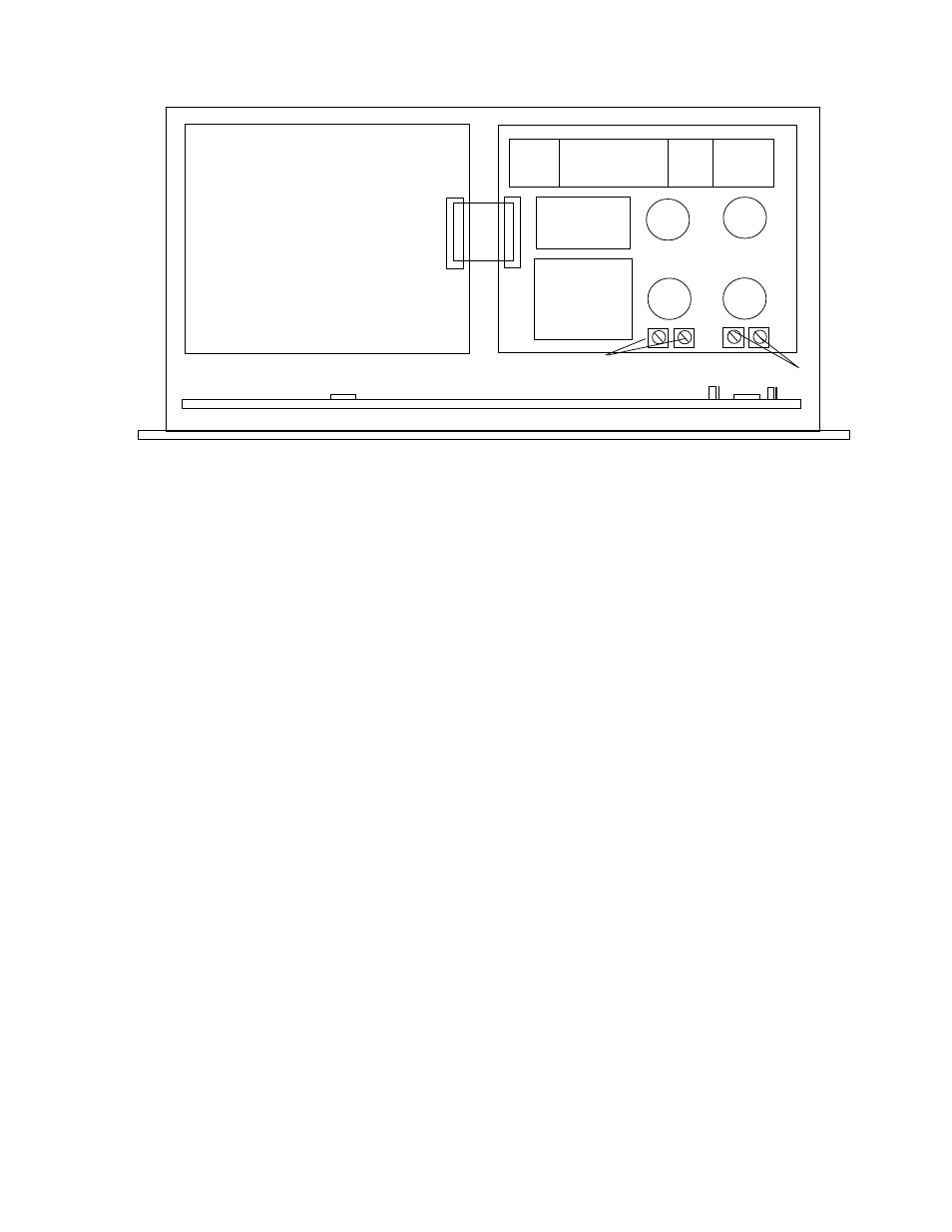
12AX7
12AX7
7044
7044
LEFT
RIGHT
DIGITAL to
ANALOG
CONVERTER
LEFT GAIN
TRIM
RIGHT GAIN
TRIM
The gains of the Wave are set at the factory. There are only 4 trimmers (2 per channel) but because the input to
the line amplifier is balanced and it is a minimum feedback design, it requires a trimmer for each phase or leg. So both
trimmers affect the gain and the "balance" of the two trimmers affect common mode rejection. Yes, this could have been
made more convenient, but it would have compromised some sonic performance.
The method to adjust these requires an oscillator, AC voltmeter, CD test disk with 1K digital full scale and a
special banana to XLR M cable that allows the oscillator to send between: a) pin 1 & pin 2, b) pin 1 & pin 3, c) pin 2 &
pin 3 (normal balanced) and d) between pin1 & pin2+pin3 (for CMRR). These tests are done with the Volume control
turned up full, the appropriate input selected (nothing else) and no amplifiers connected and the Wave well warmed up.
It is not difficult but be careful - high voltages are right around the tubes. Use an insulated screwdriver, keep one hand in
your pocket and don't touch the screwdriver to any other parts.
With the oscillator set to 1 kHz and 1 volt AC RMS and the AC voltmeter meter reading Output A of the same channel
and the special cable hooked up for:
test a) the output should read
1.3
volts. If not adjust trimmer
1
test b) the output should read
1.3
volts. If not adjust trimmer
2
Repeat this several times due to interaction between the trims
test c) should now read
4.5
volts. If not, make sure you did a) and b) correctly.
test d) should read 0.0 volts and common mode cancellation should occur.
You may have to slightly & carefully tweak either trimmer 1 or 2 to provide the deepest cancellation and you should
either switch the meter to the most sensitive scale or adjust this while listening to the output and trimming for the lowest
possible signal. If you attempt to do this listening to the output, be careful, slow and don't change any cables until you
turn off the amps. A sudden change from a tiny signal to full tilt 1K oscillator can easily blow a speaker.
Amps are off, back to using the AC voltmeter? Good, insert the test CD, select that digital input and the 1K full scale
track. You should read 2 volts now.
Jumpers marked J1, J2, J3 are used to change from the default mode where OUT 2 and OUT 3 alternate and the PHASE
function is remote controlled to OUT 2 and OUT 3 are individually controlled but this uses the button on the remote
normally used for PHASE. The diagram above shows the default mode.
There are 3 sets of 8way dip switches, 2 on the Wave logic board marked DIP1 and DIP2 and one in the remote. All 3
sets must be set identically for proper operation. These are used to set the "address" function of the remote control, IR
receiver and front panel. They should only be changed in the unlikely scenario where one of your other remote controls
and the Wave clash. They allow the Wave to use a different remote control "address". All 3 should be set the same unless
for some reason you want the front panel buttons disabled. In that case, change DIP1 to be unique.
HDCD
GAIN
OUTPUT
SELECTION
(& MUTE)
INSERT
INPUT
SELECTION
1 2 3 4
J1,J2
DIP2
DIP1
J3
PASSIVE
ANTI-
ALIAS
FILTERS
REGULATORS
& WARM-UP
DELAY
12