Boonton 4540 Peak Power Meter Quick Start User Manual
Page 8
4540 Power Meter
Quick Start Guide
PN: 98406000A
© Copyright 2008 Boonton
Page 8
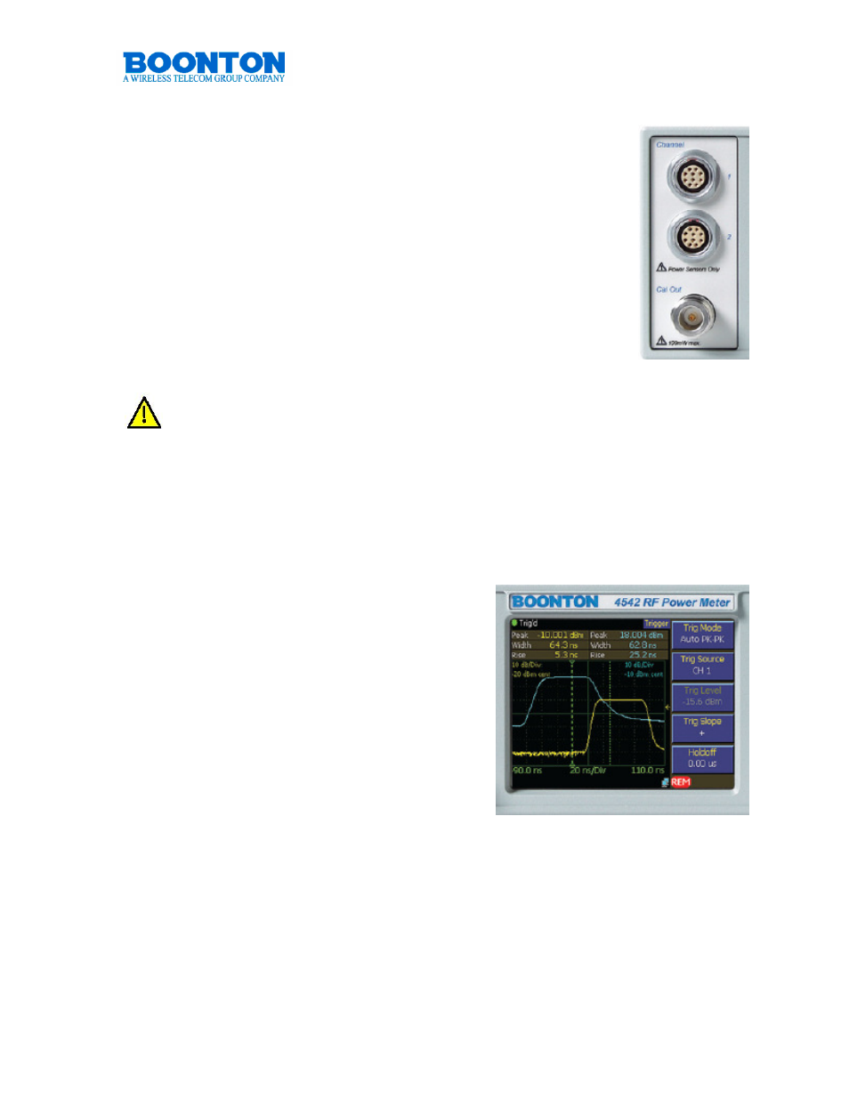
Measurement Channels
4541 consists of one, 4542 of two measurement channels. Both
systems are optionally available with the sensor and calibrator
connectors located on the rear panel. Such a configuration can be
beneficial for rack mount ATE applications The measurement
channels provide an RF range from 1 MHz to 110 GHz and offer a
dynamic range of -55 dBm to +20 dBm for Peak Power
measurements and -70 dBm to +44 dBm for CW Power
measurements. Actual measurements are dependent on the
sensors used. Both channels support a variety of Boonton Power
Sensors. A comprehensive list is provided in chapter 4540
Sensors (page 35-37)
. Sensors connected to the 4540 are
automatically detected.
Do not connect other components or power sensors of other manufacturers
to the measurement inputs. Damage will occur.
Calibrator Output
All 4540 series Peak Power Meters provide a build-in 50 MHz, -60 dBm to +20 dBm,
0.1 dB step calibrator. The calibrator allows automatic sweeping as well as manual
setting of output values. It is used to automatically calibrate sensor offset and
linearity, and can also be used as a general purpose calibration signal source.
Display
The quarter VGA display of the 4540 has a
resolution of 320x240 pixels. It provides a
detailed reading especially when in Graph
Mode. The display of the soft keys functions
can be switched on or off during
measurements. Switching off or hiding the soft
key functions increases the display area for
waveforms by another 25%. A VGA monitor
can be connected via the VGA connector found
on the rear panel of the 4540. The full screen
content will be displayed with a 320 x 240
resolution.