Hardware setup, A7n266-c chassis open alarm lead chassis – Asus A7N266-C User Manual
Page 42
42
ASUS A7N266-C User’s Manual
3. HARDWARE SETUP
Connectors
3. H/W SETUP
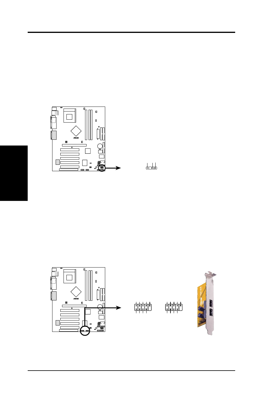
14) Chassis Open Alarm Lead (4-pin CHASSIS)
This lead is designed for chassis intrusion detection. It requires an external
detection mechanism such as a chassis intrusion monitor/sensor or microswitch.
Opening the chassis triggers the sensor and a high-level signal is sent to this lead
to record the chassis intrusion event. When not using the chassis intrusion lead,
place a jumper cap over the pins to close the circuit.
NOTE: Removing the chassis intrusion jumper without attaching any detectors
prevents boot-up of the PC.
A7N266-C
0
1
0
1
0
1
®
A7N266-C Chassis Open Alarm Lead
CHASSIS
+5V
olt
(Power Supply Stand By)
Ground
Chassis Signal
1
15) USB Headers (10-1 pin USB2_3, USB4_5)
If the USB port connectors on the back panel are inadequate, two USB headers
are available for four additional USB port connectors. Connect a 2-port USB
connector set to a USB header and mount the USB bracket to an open slot in the
chassis. (The USB connector set is optional and does not come with the
motherboard package.)
A7N266-C
0
1
0
1
0
1
®
A7N266-C Front Panel USB Headers
USB23
USB45
USB Power
USBP4
–
USBP4+
GND
NC
USB Power
USBP5
–
USBP5+
GND
1
5
6
10
USB Power
USBP2
–
USBP2+
GND
NC
USB Power
USBP3
–
USBP3+
GND
1
5
6
10