Approach Tech NVR-2018 User Manual
Page 11
9
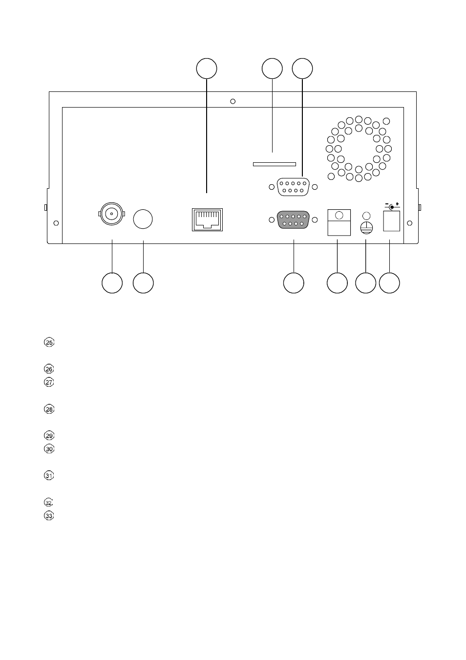
2.2 Rear View
SD Card
RS-232
ALARM
DC12V
MONITOR
AUDIO
ETHERNET
I/O
25
26 27
28 29
30
31 32 33
ETHERNET 10/100 Connector: This is one standard RJ-45 connector for 10/100 Mbps Ethernet
networks.
SD CARD Slot: This is used for system software updating and archiving/accessing critical images.
RS-232
Port: The RS-232 communication port functions as a connector to an external control device.
Please refer to RS-232 Protocol for more details.
MONITOR
Connector: The connector provides the unit’s composite video live signal if connected to a
display device.
AUDIO
OUT:
This provides the unit’s audio signal to a speaker.
ALARM I/O: This is a 9-PIN D-SUB connector including GROUND, ALARM OUT, DISK FULL, and
RECORD IN for connecting with external devices. Please refer to the next section for details.
Wire Catch: The wire catch secures the power cord and keeps it in place (so that it does not droop or
hang loosely).
Ground Screw’s: The ground screw is for chassis terminal.
Plug Inlet: The inlet connects to an external power supply. Connect 12 V DC UL Listed Class 2 Power
Supply.