Testing the assembly – Agilent Technologies E1364A User Manual
Page 45
Testing the
Assembly
You can use the tests and checks in Table 4-2 to isolate the problem. See
Figure 3-1 in Chapter 3 or Figure B-1 in Appendix B for locations of
replaceable parts, depending on the serial number of your switch module.
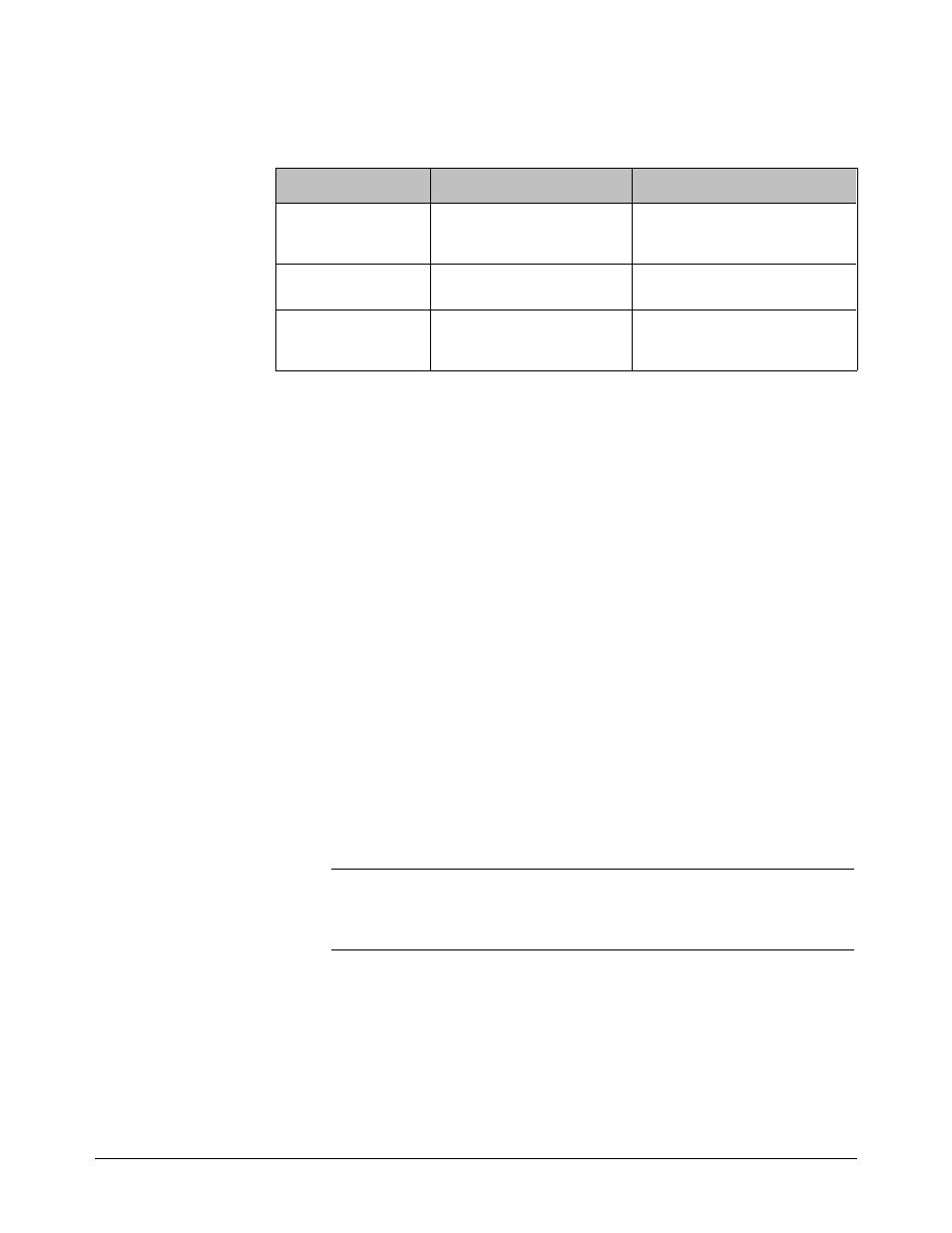
Table 4-2. E1364A Tests/Checks
Test/Check
Reference Designator
Check:
Heat Damage
- - - - - - - - - -
Discolored PC boards
Damaged insulation
Evidence of arcing
Switch/Jumper
Settings
JM13, JM14, ..., JM26
SP1
IRQ Level setting
LADDR setting
Switch PCA
F1, F2
P1, J1
K100, K101, ..., K115
Fuse continuity
Connector contacts
Relay contact resistance
Checking for Heat Damage
Inspect the switch for signs of abnormal internally generated heat such as
discolored printed circuit boards or components, damaged insulation, or
evidence of arcing. If there is damage, do not operate the switch until you
have corrected the problem.
Checking Switches/Jumpers
Verify that the logical address setting is set correctly (factory set at 120).
Verify that the interrupt priority jumpers are set correctly (factory set at
level 1). See the E1364A User’s Manual for information.
Checking the Switch PCA
Use the replaceable parts locator (Figure 3-1 or B-1, depending on the
serial number of your switch module) to check the following:
•
Verify that fuses F1 and F2 are good.
•
Check the closed-channel resistance of all relays using the procedure
in Chapter 2. Replace any bad relays.
•
Check connectors P1 and J1 for damage.
NOTE
If the preceding steps fail to isolate the problem, use the schematics
included with this manual to perform component-level troubleshooting.
Chapter 4
Service 45