Memory subsystem architecture – HP ProLiant BL680c G7 Server-Blade User Manual
Page 50
Hardware options installation 50
DIMM pairs (4A/5A, 12B/16B, 2C/7C, and 10D/14D), as long as they are installed at the end
point of the DDR3 channel.
AMP modes Advanced ECC, DDDC, HP Memory Quarantine, Online Spare, and Mirrored Memory have
further requirements beyond the ones listed here. For additional memory configuration requirements, see the
corresponding AMP sections:
•
Advanced ECC memory population guidelines (on page
•
Double Device Data Correction (on page
•
•
Online Spare memory population guidelines (on page
•
Mirrored Memory population guidelines (on page
Memory subsystem architecture
The Intel® Xeon® E7 family and 7500 series processor memory architectures are designed to take
advantage of multiple stages of memory interleaving to reduce latency and increase bandwidth.
Each Intel® Xeon® E7 family and 7500 series processor contains two memory controllers as shown in the
illustration below. Each memory controller has two SMI buses operating in Lockstep mode. Each SMI bus
connects to an SMB or buffer as shown in the illustration below. The buffer converts the SMI to DDR3 and
expands the memory capacity of the system. Each buffer has two DDR3 channels and can support up to four
DIMMs for a total of 16 DIMMs per processor, or 64 DIMMs per HP ProLiant BL680c G7 Server Blade with
four processors installed.
Memory speed is not affected by number of DIMMs, ranks, or voltage. All DIMMs run at the highest possible
speed for a given processor.
DDR3 memory speed is a function of the QPI bus speed supported by the processor:
•
Processors with a QPI speed of 6.4 GT/s run memory at 1066 MT/s.
•
Processors with a QPI speed of 5.6 GT/s run memory at 978 MT/s.
•
Processors with a QPI speed of 4.8 GT/s run memory at 800 MT/s.
Successive cache lines are interleaved between the DIMMs and the Lockstep SMI channels of the two
memory controllers in the processor such that adjacent cache lines reside on different memory controllers,
SMIs, DIMMs, and DIMM ranks for better performance. To take advantage of this feature, DIMMs should be
populated evenly between all SMI channels. If an SMI channel pair has more DIMMs than others, the extra
memory on that SMI channel pair does not benefit from the interleaving mechanism across memory
controllers.
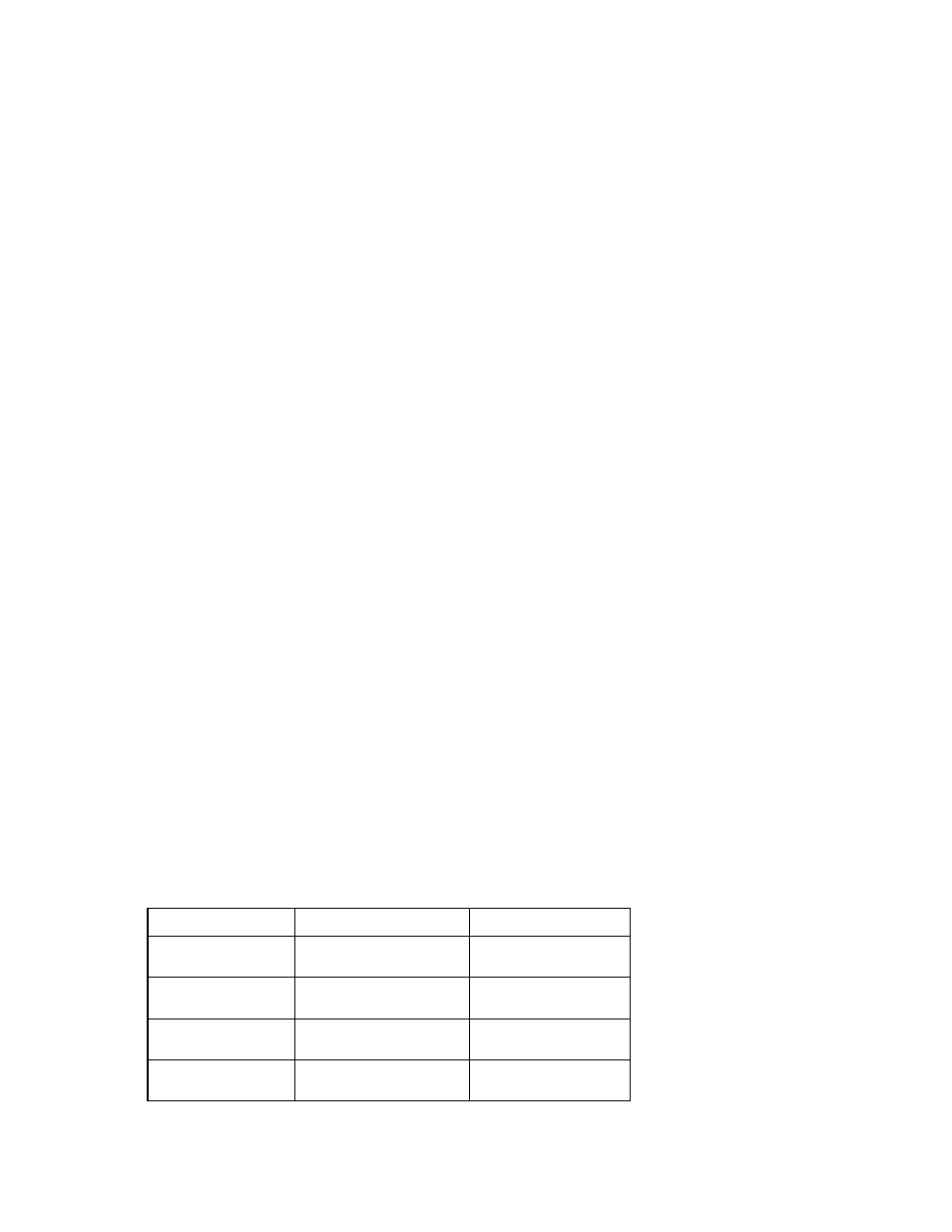
Memory architecture for processors 1 and 3
Channel
Slot
Slot number
1
A
E
4
3
2
C
G
2
1
3
A
E
5
6
4
C
G
7
8